KESSEL-Hebeanlage Aqualift S für fäkalienfreies Abwasser zur Unter-/Überflurinstallation
←
→
Transkription von Seiteninhalten
Wenn Ihr Browser die Seite nicht korrekt rendert, bitte, lesen Sie den Inhalt der Seite unten

ANLEITUNG FÜR EINBAU, BEDIENUNG UND WARTUNG
D Seite 1
KESSEL - Hebeanlage Aqualift S GB Page 17
für fäkalienfreies Abwasser zur Unter-/Überflurinstallation F
I
Page 33
Pagina 49
NL Pagina 65
Best. Nr. 28500 / 28530 / 28541 / 28550 PL Strona 81
Produktvorteile
ufsatzstück teleskopisch höhenverstellbar,
A
drehbar und neigbar
Anpassung der Abdeckung an das Fliesenraster
Pressdichtungsflansch zum Anschluss von Feuchtigkeitsabdichtungen
Anschluss von weiteren Zuläufen
durch Anbohren der seitlichen Flächen
Als Doppelhebeanlage für erhöhten Schmutzwasseranfall
Installation Inbetriebnahme Einweisung
der Anlage wurde durchgeführt von Ihrem Fachbetrieb:
Änderungsstand: 2019/12
Sachnummer: 010-047
Name/Unterschrift Datum Ort Stempel Fachbetrieb Techn. Änderungen vorbehalten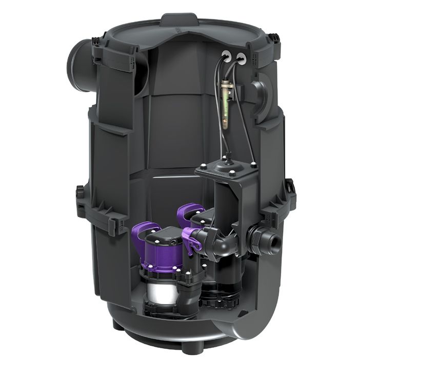
                                                  Sicherheitshinweise
Die in dieser Betriebsanleitung enthaltenen Sicherheitshinweise, die für Einbau, Betrieb, Wartung und Instandsetzung des Aggregats
beachtet werden müssen, sind mit folgenden Symbolen gekennzeichnet:

                 Allgemeines Gefahrensymbol nach ISO 3864-B-3-1 zur Kennzeichnung von Gefährdungen für Personen.

                 Gefahrensymbol nach ISO 3864-B-3-6 zur Warnung vor elektrischer Spannung.

  Achtung        Dieses Wort kennzeichnet Sicherheitshinweise, deren Nichtbeachtung Gefahren für die Maschine und deren Funktion
                 hervorrufen kann.

Diese Bedienungsanleitung muss ständig an der Anlage vorhanden sein.

 Sehr geehrter Kunde,

 wir freuen uns, dass Sie sich für ein Produkt von KESSEL entschieden haben.
 Die gesamte Anlage wurde vor Verlassen des Werkes einer strengen Qualitätskontrolle unterzogen. Prüfen Sie bitte dennoch sofort, ob die Anlage
 vollständig und unbeschädigt bei Ihnen angeliefert wurde. Im Falle eins Transportschadens setzen Sie sich mit Ihrem Lieferanten in Verbindung.

 Vor Montage und Inbetriebnahme der KESSEL-Abwasserstation Aqualift S ist diese Einbau- und Bedienungsanleitung sorgfältig zu lesen.

 KESSEL AG

                                                             2 / 96                                                                    2019/12
                                    Inhaltsverzeichnis
1. Allgemein             1.1   Verwendung		                                    Seite    4
                         1.2   Anlagenbeschreibung		                           Seite    4
                         1.3   Funktionsweise von Duo-Anlagen		                Seite    4
                         1.4   Verlegen des Druckschlauchs zum Schaltgerät		   Seite    4
                         1.5   Anschlüsse		                                    Seite    5

2. Einbau             2.1   Einbau in die Bodenplatte		                     Seite    6
                         2.2   Vertiefter Einbau in die Bodenplatte		          Seite    7
                         2.3   Einbau in drückendes Wasser		                   Seite    8
                         2.4   Aqualift S Duo zur Überflurinstallation		       Seite    9
                         2.5   Einbau der Pumpe		                              Seite    9
                         2.6   Überprüfen der Tauchrohreinstellung		           Seite    9
                         2.7   Positionierung der Alarmsonde		                 Seite    9
                         2.8   Einbauvorschlag		                               Seite    10

3. Reinigung / Wartung   3.1   Ausbau der Pumpe(n)		                           Seite    11
                         3.2   Einbau der Pumpe(n)		                           Seite    11
                         3.3   Wartung		                                       Seite    12
                         3.4   Wartung der integrierten Rückstauklappen		      Seite    12
                         3.5   Überprüfung der Entlüftungsbohrung		            Seite    12

4. Technische Daten      4.1   Maßzeichnungen		    Seite                                13
                         4.2   Leistungsdiagramm		 Seite                                14

5. Hilfe bei Störungen				                                                     Seite    15

Konformitätserklärung / DOP			                                                 Seite    96

                                         3 / 96                                        2019/12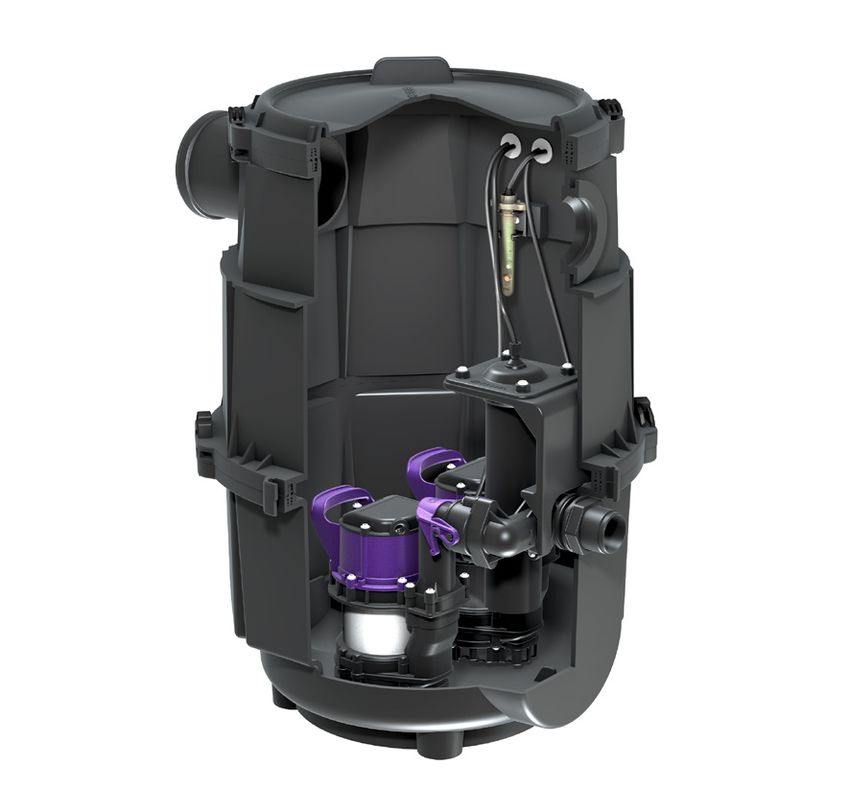
1. Allgemein
1.1 Verwendung Die KESSEL Hebeanlage Aqualift S ist in Überflurinstallation
Fäkalienfreies Schmutzwasser, welches folgenden Varianten erhältlich: (Best.Nr. 28541)
un
terhalb der Rückstauebene anfällt ist
gemäß DIN EN 12056 über eine Abwasser- Einbau in die Bodenplatte Die KESSEL Hebeanlage Aqualift S Duo
hebeanlage zu entsorgen. (Best.Nr. 28500 / 28530 / 28550) besteht aus dem Pumpenbehälter und einer
geruchsdichten Abdeckung. Die Steuerung
1.2 Anlagenbeschreibung Die Hebeanlage besteht aus dem Pumpen der beiden Pumpen erfolgt über Tauchrohr
Die KESSEL-Schmutzwasserhebeanlage behälter mit integriertem Preßdichtungs- und Drucksensor im Schaltgerät.
Aqualift S ist beständig gegen haushalts- flansch, einem teleskopischen Aufsatz-
übliche Säuren und Laugen (ph-Wert von stück und einer Abdeckplatte mit Schlitz- 1.3 Funktionsweise von Duo-Anlagen
6,5-10) sowie gegen Kälte und Heiss rost (Klasse A), wahlweise einer tagwasser- Die Pumpen sind abwechselnd in Betrieb,
wasser. Kondensatabwasser aus Brenn- dichten Abdeckplatte Klasse A. bei erhöhtem Schmutzwasserzufluß oder
wertgeräten ist vor der Einleitung in die Die maximale Grundwasserbeständigkeit bei Ausfall einer der beiden Pumpen schal-
Anlage zu neutralisieren oder ausreichend beträgt 2 m. tet die zweite Pumpe automatisch zu.
zu verdünnen. Die Einleitung von Fäkali-
en oder fäkalienhaltigem Abwasser sowie Folgende Versionen sind erhältlich mit: 1.4 Verlegen des Druckschlauchs zum
brennbarer oder explosiver Flüssigkeiten/Be- - 1 Pumpe mit Schwimmerschalter Schaltgerät
standteile ist untersagt. - 1 Pumpe mit Tauchrohr und Bei Anlagen mit Tauchrohr und Druck-
Drucksensor im Schaltgerät sensor im Schaltgerät ist darauf zu achten,
- 2 Pumpen mit Tauchrohr und dass der Druckschlauch stetig steigend
Drucksensor im Schaltgerät verlegt wird um Fehlfunktionen durch Kon-
densat zu vermeiden.
Optional kann ein Kleinkompressor (Art.-
Nr. 28048) angeschlossen werden.
4 / 96 2019/12
                         1. Allgemein
                                        1.5 Anschlüsse
                                        Druckanschluss: R 11/2 Aussengewinde oder
                                        Druckrohr D = 40 mm für PVC-Klebever-
                                        bindung. Drucklose Rohranschlüsse (z.B.
                                        HT-Rohr) sind nicht für Druckleitungen zu-
                                        lässig.
                                        Durch Anbohren des Grundkörpers mit einer
                                        Sägeglocke können Anschlüsse bis DN
                                        100 angebracht werden (siehe Bild unten).
                                        Die Mindesthöhe Unterkante Zulauf darf
                                        nicht tiefer liegen als das Einschaltniveau
                                        muss aber mind. 145 mm (Tronic-Variante)
                                        zur Unterkante Behälter betragen. Mindest-
                                        höhe Unterkante Tauchrohr bis Behälter-
DN100

                                        boden beträgt 100 mm ist werkseitig ein-
                                        gestellt.
        mind.145   100

                          5 / 96                                           2019/12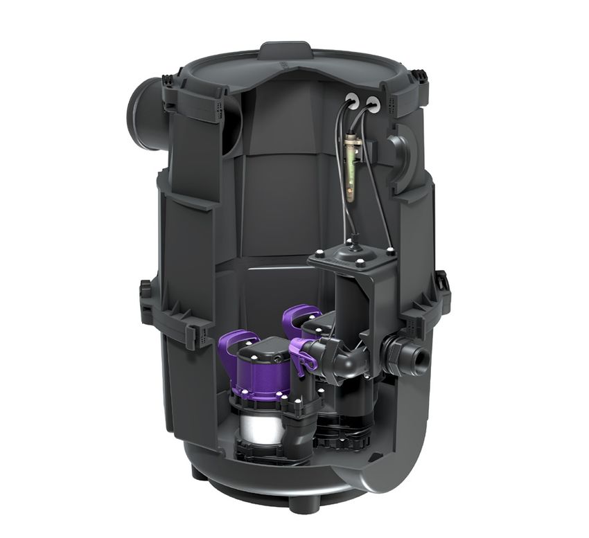
2. Einbau
Vor dem Einbau sind alle Teile auf Trans- fassung, Schwimmer, Tauchrohr anbringen Die beiliegende Profil-Lippendichtung in
portschäden zu überprüfen. um Fehlfunktionen zu vermeiden. die Nut des Zwischenstückes einlegen,
Für den Anschluss der elektrischen Leitun- einfetten und das Aufsatzstück montieren.
2.1 Einbau in die Bodenplatte gen ist bauseits ein Kabelleerrohr vorzuse- Durch das teleskopische Aufsatzstück kann
Der Pumpenbehälter ist waagrecht auszu- hen (Abb. 3). Das Leerrohr kann in die im die KESSEL Hebeanlage Aqualift S stufen-
richten. Falls erforderlich, seitliche Zuläufe Zwischenstück vorgesehene Kabeldurch- los an die vorhandene Einbautiefe angepaßt
anbringen. Dazu können die ebenen Flä führung, aber auch an beliebiger Stelle werden. Bodenneigungen bis zu 5° können
chen des Behälters, ggf. auch das Zwi- durch Anbohren des Behälters (Abb. 1/2) ausgeglichen werden. Eine Ausrichtung der
schen- und Aufsatzstück (max. DN 50), montiert werden. Abdeckung, z.B. an das Fliesenraster ist
mit der KESSEL-Sä geglocke (Art.-Nr. Bei Verwendung eines Verlängerungs- möglich (Abb. 4).
50100) angebohrt werden. Anschließend stückes (Art. Nr. 83070) ist darauf zu ach-
in die Bohrung die passende elastomere ten, dass das Kabelleerrohr oberhalb der
Dichtung einsetzen und Zulaufleitung ein- Bodenplatte verlegt wird.
schieben (Abb. 1/2).
DN50
Abb. 4
Achtung
Zum Erreichen der minimalen
Abb. 1 Abb. 2 Einbautiefe ist das Aufsatzstück auf das erfor-
derliche Maß zu kürzen. Vor der endgültigen
Achtung
Abb. 3 Ausrichtung müssen im Bereich der Kabel-
Die Zuläufe nicht im Bereich der Niveauer- durchführung sowie dort, wo ggf. zusätzliche
6 / 96 2019/12
2. Einbau
Zuläufe angebracht wurden Aussparungen Abdeckplatte ist eine Entlüftungsleitung kann.
angebracht werden siehe Abb. 5. DN 50 erforderlich. Behälter erst nach b) Verlegen der Fliesen z.B. mit PCI-Silco-
Anschluss sämtlicher Rohrleitungen und ferm S (selbsthaftendes Silikon). Damit
Dichtheitsprüfung im Betonbett eingießen. kann gerade für dickere Fliesen ein dün-
nes Kleberbett realisiert werden.
mind. 40mm
5-10mm Einbau von Abdeckungen mit wählba-
rer Oberfläche Verlegen von Naturstein
(Marmor, Granit, Agglomarmor)
Bei den Abdeckungen mit wählbarer Ober- a) Grundierung der Abdeckplatte z.B. mit
Abb. 5
fläche besteht die Möglichkeit, bauseits PCI-Flächengrund 303, Verlegung der
Die Lippendichtung muss in der Abdeck- Fliesen oder Natursteine in die Abdeckung Natursteinplatten z.B. mit PCI-Carralit.
platte angebracht werden. Dabei ist zu be- einzulegen und sie damit an den Boden- b) Verlegung der Natursteinplatten z.B. mit
achten, dass Dichtlippe und Zentriernase belag des Raumes anzupassen. Zur Ver- PCI-Carraferm (spezielles Natursteinsili-
bei der Montage nach oben schauen. Die legung der Fliesen eignen sich Produkte, kon). Anwendungsbereiche analog zu 1.
Zentriernase ist in die Aussparung einzule- z.B. von PCI, Schomburg, Deitermann. Um
gen (siehe Abb. 6). eine problemlose Verarbeitung und Haf-
Bei Verwendung der tagwasserdichten tung zu erzielen, empfehlen wir folgende 2.2 Hebeanlage Aqualift S zum vertief-
Vorgehensweise: ten Einbau in die Bodenplatte
(mit Verlängerungsstück Art.Nr. 83075)
Verlegen von Fliesen Je nach Einbautiefe können ein oder zwei
a) Grundierung der Abdeckplatte z.B. mit Verlängerungsstücke zwischen Aufsatz-
PCI-Flächengrund 303. Nach entspre- und Zwischenstück eingesetzt werden. Die
chender Ablüftezeit Verlegung der Flie- jeweiligen Dichtungen sind entsprechend
sen z.B. mit PCI-Flexmörtel. Diese Ver- einzufetten.
legung ist vor allem bei dünneren Fliesen
geeignet, da eine Aufspachtelung auf die
Abb. 6 erforderliche Höhe durchgeführt werden
7 / 96 2019/12
2. Einbau
2.3 Einbau in drückendes Wasser usw. zu durchbrechen, sind auch diese
Ist der Einbau in drückendem Wasser er- Durchdringungen wasserundurchlässig
forderlich, kann die KESSEL Hebeanlage herzustellen.
Aqualift S einfach und problemlos abge- Die beiliegende Profil-Lippendichtung in
dichtet werden. Dazu wird zwischen dem die Nut des Zwischenstückes einlegen und
Gegenflansch aus Kunststoff und dem am einfetten. Anschliessend das Aufsatzstück
Grundkörper integrierten Preßdichtungs- montieren (siehe Abb. 8).
flansch eine Dichtungsbahn eingeklemmt Dem Verlängerungsstück beiligende Ein-
und mit den beiliegenden Schrauben ver- bauanweisung beachten.
schraubt. Als Dichtungsbahn kann jede
bauseits verwendete Dichtfolie verwendet
werden. Bei Einbau in WU-Beton (weiße
Wanne) bietet KESSEL zusätzlich eine pas-
sende Dichtungsbahn aus Naturkautschuk Gegenflansch
Gegenflansch
NK/SBR mit Gegenflansch an, bei welcher Dichtungsbahn
Dichtungsbahn
Abb. 8
die Bohrungen zum Verschrauben bereits
ausgestanzt sind (siehe Abb. 7). Die Zube-
hörteile sind Bestandteil von Art.Nr. 83075.
Die maximale Grundwasserbeständigkeit
beträgt 2 m. Pressdichtungs
Eine Verlegung der Dichtebene ins Aufsatz- -flansch
Pressdichtungs
stück erfordert einen veränderten Aufbau -flansch
bei dem das Verlängerungsstück mittiger
Flansch zum Tragen kommt (siehe Abb. 9).
Falls es notwendig ist, die wasser- Preßdichtungsflansch LW 400 Dichtungsbahn
dichte Betonwanne beispielsweise für den Abb. 7
Anschluss von Zuläufen, Kabelleerrohren, Abb. 9
8 / 96 2019/12
2. Einbau
2.4 KESSEL Hebeanlage Aqualift S Duo • H für Anlage zur freien Aufstellung
zur Überflurinstallation (Art.Nr. 28541) (Art.Nr. 28541) beträgt 12 cm (Abb. 11)
Bei Abweichungen Gleitmutter an der
Die Ausführung zur freien Aufstellung wird Verschraubung der Tauchrohrbefestigung
betriebsbereit geliefert und muß nur noch lösen und Tauchrohr in vorgegebener Höhe
an die bauseits verlegten Abwasserleitun- (H) fixieren.
gen angeschlossen werden.
Um die Funktion der Hebeanlage zu ge- 2.7 Positionierung der Alarmsonde (Art.
700
währleisten, ist eine Entlüftungsleitung (DN Nr. 28530 / 28541 / 28550)
580
575
610
50 für Normalbetrieb, DN 70 im Anschluss
420
an einen Fettabscheider) zu verlegen. Den
258
Behälter mit den mitgelieferten 4 Befesti
gungselementen am Boden verschrauben.
Diese dienen zur Schalldämmung. (Abb.9)
2.5 Einbau der Pumpe
Um Transportschäden zu vermeiden, wer-
den die Pumpen separat verpackt und Art. Nr. 28541 Abb. 11
müssen vor Inbetriebnahme - wie in Kap. Vor Inbetriebnahme ist die optische Sonde wie
3.2 - beschrieben, eingebaut werden. in Abb. 10 und 11) einzuklipsen.
2.6 Überprüfen der Tauchrohreinstel-
242
lung (Art.Nr. 28541 / 28530 / 28550)
H
Der Abstand H zwischen Unterkante
Tauchrohr und Behälterboden ist vor Inbe-
triebnahme zu überprüfen: Art.Nr. 28530 / 28550 Abb. 10
• H für Unterfluranlage (Art.Nr. 28350/
28550) beträgt 10 cm (Abb. 10)
9 / 96 2019/12
2. Einbau
2.8 Einbauvorschlag
522 mm
KESSEL-Schmutzwasserhebeanlage Aqualift S Tronic Mono (Art.N. 28550)
Pressdichtungsflansch
Teleskopisches Aufsatzstück
Dichtungsbahn
+Verlängerungs und Dichtungsset (Art.-Nr. 83075) zum Einbau im WU-Beton
10 / 96 2019/12 und Wartung
3. Reinigung
Nach DIN 12056 ist eine Wartung durch einen Nach Erledigung der Wartungsarbeiten alle de- 3.2 Einbau der Pumpe(n)
Fachkundigen (Fachfirma) in folgenden Zeit- montierten Teile wieder montieren, einen Pro- Vor dem Wiedereinbau sämtliche Dichtflächen
abständen durchzuführen: belauf durchführen und die Anlage wieder in reinigen. Die Lippendichtung im Auslauf ein
• nach 3 Monaten bei Anlagen in gewerbli- Betrieb nehmen. Wartungsprotokoll anfertigen. fetten. Die Pumpe mit den beiden Nuten im Ge
chen Anwendungen. häuseboden auf die Führung im Behälter stellen
• nach 6 Monaten bei Anlagen in Mehrfami- 3.1 Ausbau der Pumpe(n) und vorschieben, bis das Druckrohr der Pumpe
lienhäusern. in den Auslauf des Behälters eingeführt werden
• nach 1 Jahr bei Anlagen in Einfamilienhäusern. Rückstauklappe
kann (Abb. 13). Den Einhandverschluss verrie-
KESSEL empfiehlt den Abschluss eines War- mit Pfeil nach geln. Bei der Aqualift S Duo-Hebeanlage wird
unten einbauen
tungsvertrages mit dem einbauenden Unterneh- genauso verfahren, nur daß jeweils die innen-
men oder dem KESSEL-Werkskundendienst. liegende Nut auf die Führungsschiene gestellt
wird. Das Kabel mit dem Stecker durch das
Bei der Wartung sind im Allgemeinen fol- Kabelleerrohr mit Hilfe eines Zugdrahtes ein-
gende Arbeiten auszuführen: ziehen und an die Steckdose anschließen.
• Prüfung aller Verbindungsstellen auf Dicht-
heit
Mono
• Betätigung der Schieber, gegebenenfalls
einfetten und nachstellen
• Öffnen und Reinigen des Rückflussverhin- Entlüftungsbohrung
ders
• Reinigung der Entwässerungspumpe, Prü- Abb. 12 gilt auch ohne Schwimmer.
fung des Laufrades und der Lagerung Durch Lösen des Einhandverschlusses kann
• Reinigung der Entlüftungsbohrung am die Pumpe schnell und ohne Werkzeuge ent- Duo
Druckstutzen. nommen werden. Die Rückschlagklappe,
• Innenreinigung des Behälters bei Bedarf dann im Druckstutzen des Behälters, verhin-
• Prüfung der elektrischen Anschlüsse auf dert, dass Abwasser, welches sich noch in der
Funktion Druckleitung befindet, in die Anlage zurück-
läuft.
Abb. 13
11 / 96 2019/12 und Wartung
3. Reinigung
Bei den Ausführungen mit Schaltgerät ist das die Rückstauklappe entnommen und gereinigt
Sondenkabel bzw. der Schlauch für die pneu- werden.
matische Niveauerfassung ebenfalls durch Auf diese Weise ist auch ein ungehinderter Zu
das Kabelleerrohr zu ziehen. Den Behälter gang zum Reinigen der Druckleitung möglich.
mit Wasser auffüllen und die Funktion des
Schwimmerschalters, bzw. der Sonden oder Achtung
des Tauchrohres überprüfen. Schlitzrost oder
Abdeckplatte einlegen. Beim Einbau darauf achten, daß die Klappe
mit dem Pfeil nach unten montiert wird.
3.3 Wartung
Vor jeder Arbeit an der Pumpe 3.5 Überprüfen der Entlüftungsbohrung
Achtung NETZSTECKER ZIEHEN! Bei jeder Wartung ist die Entlüftungöffnung
Dazu nach Pumpenentnahme den Ansaug- mm (Abb. 14) auf freien Durchgang zu prü-
korb abschrauben, Ansaugdeckel abnehmen fen. Eine verstopfte Entlüftungsöffnung kann
und Flügelradraum reinigen. Den Schwimmer- zur Reduktion der Förderleistung der Pumpe
schalter sowie die Niveausonden oder das führen.
Tauchrohr und Alarmsonde regelmäßig auf
Verschmutzungen prüfen und ggf. reinigen.
Die Pumpe niemals selber öffnen (nur durch
einen Fachmann), da bei unsachgemäßem 2
Eingriff die Abdichtung der Pumpe beschä-
digt werden und Öl in das Abwasser gelangen
könnte.
3.4 Wartung der integrierten Rückstau-
klappen
Die Pumpe entnehmen. Nach dem Ausbau Abb. 14
der Pumpenbefestigung (Lösen der beiden
Kreuz-Schlitzschrauben, siehe Abb. 12) kann
12 / 96 2019/12
                                                                        4. Technische Daten
4.1 Maßzeichnungen:

a

                                                                                                   bis 202
                                                                                                   von 27
                                                                                              b
              bis 202
              von 27

                                                                                                               400
                                 400

                                                                                              T
    T

                                                                  Aqualift S                                                               Aqualift S Tronic

                                                                                                  454
                                                                                                        330

                                                                                                                             DA 40
        454
              330

                                                   DA 40

                                                                                                                                     258
                                                            258

                                                                  Unterflurinstallation
                    200

                                                                                                                                           (28550)
                          85

                                                                  (28500)
                                     590                                                                       590

c                                                                                             d
        bis 202
        von 27

                               400

                                                                                                   100
                                                                                                   DN

                                                                                                                     DA 40

                                                                                                                               720
                                                                                                                             575
                                                                                                        530

                                                                                                                       258
 T

                                                                  Aqualift S Duo                                                          Aqualift S Duo
     454
           330

                                           DA 40

                                                      258

                                                                  Unterflurinstallation                                                    Überflurinstallation
                                                                  (28530)                                     500                          (28541)
                               590

                                                                                    13 / 96                                                              2019/12
                                                                      4. Technische Daten
4.2 Pumpenleistungsdiagramm Hebeanlage Aqualift S

                                                                                                                                          KTP 500         GTF 500
H [m]
                                                                                                                 Gewicht                  6,7 kg          6 kg
    7
                                                                                                                 Leistung P1 / P2         480 W / 310 W   650W / 400 W
    6                                                                                                            Drehzahl                 2800 min-1      2750 min-1
    5                                                                                                            Betriebsspannung         230 V; 50 Hz    230 V; 50 Hz

    4                                                                                                            Nennstrom                2,2 A           2,9 A
                                                                                                                 Förderleistung max.      9 m3/h          12 m³/h
    3
                                                                                                                 Förderhöhe max.          8m              8m
    2                                                                                                            Förderguttemperatur      35°C            35°C
    1                                                                                                            (dauerhaft) max.
                                                                                                                 Schutzart                IP68            IP68
                    1         2           3           4          5          6           7 Q [m3/h]               Schutzklasse             I               I
                                                                                                                 Motorschutz              integriert      integriert
H             7,5       6,9   6,6   6,2   5,7   5,3       5,0   4,5   4,1   3,7   3,3    3,0   2,5   2,1   1,2
                                                                                                                 Erforderliche Absiche-   10 A            16 A
Q [m³/h]      0,5       1,0   1,5   2,0   2,5   3,0       3,5   4,0   4,5   5,0   5,5    6,0   6,5   7,0   8,1
                                                                                                                 rung (Leitungsschutz)
Q [l/s]       0,1       0,3   0,4   0,6   0,7   0,8       1,0   1,1   1,3   1,4   1,5    1,7   1,8   1,9   2,3
                                                                                                                 Betriebsart              S1              S1
H geglättet   7,4       7,0   6,6   6,2   5,8   5,3       4,9   4,5   4,1   3,7   3,3    2,9   2,5   2,1   1,2

                                                                                  14 / 96                                                                              2019/12
Störungen
5. Hilfe bei
Störung mögliche Ursache Abhilfemaßnahmen
Pumpe läuft nicht - keine Netzspannung vorhanden Netzspannung prüfen
- Sicherung defekt Sicherung austauschen
- Netzleitung beschädigt Reparatur nur durch KESSEL-Kundendienst
- Schwimmerschalter defekt Schwimmerschalter komplett
austauschen (Art.-Nr. 28012) oder Reparatur
durch KESSEL-Kundendienst
- Entlüftungsbohrung verstopft Entlüftungsbohrung reinigen
Laufrad blockiert Verunreinigungen, Fest- und Grobstoffe Reinigung der Pumpe
haben sich zwischen Laufrad und Saug- (siehe Kapitel 3)
flansch festgesetzt.
verminderte Förderleistung - Ansaugkorb verstopft Reinigung der Pumpe (siehe Kapitel 3)
- Verschleiß des Ansaugflansches Ansaugflansch auswechseln
- Verschleiß des Laufrades Laufrad auswechseln
- Entlüftungsbohrung verstopft Entlüftungsbohrung reinigen
Pumpe wird heiß und schaltet ab - Stromaufnahme zu hoch - Druckleitung auf über 0,5 m Förderhöhe
- Förderhöhe < 0,5 m erhöhen
- Alternativ kann ein Ersatzflügelrad einge-
baut werden. Dadurch vermindert sich
jedoch geringfügig die Förderhöhe
15 / 96 2019/12Führend in Entwässerung
6 4
Privater Wohnungsbau
ohne Kanalanbindung
1 2 3 4 5
Öffentlicher Bau 1 2 3 4 5
z.B. Krankenhaus Öffentlicher Bau
z.B. Freizeitanlagen
1 2 3 4 5
Gewerblicher Bau
z.B. Hotel
4 5
Gewerblicher Bau
z.B. Industriebau
2 3 5
Gewerblicher Bau
z.B. Tankstellen
1 2 3 4
Privater Wohnungsbau
Ein- und Mehrfamilienhaus
1 Rückstauverschlüsse 2 Rückstauhebeanlagen 3 Hebeanlagen
4 Abläufe / Rinnen 5 Abscheider 6 KleinkläranlagenINSTRUCTIONS FOR INSTALLATION, OPERATION AND MAINTENANCE
KESSEL lifting station Aqualift S
for wastewater with sewage for underground/overground installation
Product advantages
elescopic height adjustment of upper cover section,
T
can be turned and tilted
Adaptation of the cover to the tile pattern
Compression seal flange for the connection of humidity seals
Connection of further inlets
by pre-scoring the areas at the side
As a twin lifting station for increased soiled water occurrence
Installation Initial operation Instruction
for the system was carried out by your specialist company:
Change status: 2019/12
Part number: 010/-047
Name/Signature Date City Stamp of specialist company Subject to technical modifications
                                                       Safety instructions
The safety instructions contained in this manual that have to be heeded for the installation, operation, maintenance and repair of the unit
are marked with the following symbols:

                  General hazard symbol in accordance with ISO 3864-B-3-1 for indicating personal hazard

                  Hazard symbol in accordance with ISO 3864-B-3-6 warning of electrical voltage.

  Caution:        This word indicates safety instructions the non-observance of which can cause hazards for the machine and its function.

This operating manual must always be available at the unit.

 Dear customer,

 We are pleased that you have decided to buy a KESSEL product.
 The entire system was subjected to a stringent quality control before it left our factory. Nevertheless, please check immediately whether the system
 has been delivered to you complete and undamaged. In case of any transport damage, please contact your supplier.

 Before installation and initial operation of the KESSEL wastewater station Aqualift S please read these installation and operation instructions
 carefully.

 KESSEL AG

                                                                18 / 96                                                                        2019/12
Table of contents
1. General points 1.1 Use............................................................................................... .Page 20
1.2 System description....................................................................... .Page 20
1.3 Duty – Stand by operation of twin pump systems........................ .Page 20
1.4 Connection of air pressure tube to control unit............................ .Page 20
1.5 Connections................................................................................. .Page 21
2. Installation 2.1 Installation in the ground plate .................................................... .Page 22
2.2 Recessed installation in the ground plate .................................... .Page 23
2.3 Installation in water load .............................................................. .Page 23
2.4 Aqualift S Duo for installation above ground ............................... .Page 25
2.5 Installation of the pump................................................................ .Page 25
2.6 Checking submersible pipe setting.............................................. .Page 25
2.7 Positioning the alarm probe.......................................................... .Page 25
2.8 Installation suggestion.................................................................. .Page 26
3. Cleaning / Servicing 3.1 Removing the pump(s).................................................................. .Page 27
3.2 Installing the pump(s).................................................................... .Page 27
3.3 Servicing....................................................................................... .Page 28
3.4 Servicing the integrated backwater valves................................... .Page 28
3.5 Checking the venting pipe............................................................ .Page 28
4. Technical data 4.1 Dimensional drawings.................................................................. .Page 29
4.2 Capacity diagram......................................................................... .Page 30
5. Troubleshooting ...................................................................................................... .Page 31
Declaration of conformity/DOP ...................................................................................................... .Page 96
19 / 96 2019/12
1. General points
1.1 Use The lifting station comprises a pump tank 1.3 Duty – Stand by operation of twin
Soiled water without sewage which occurs with integrated compression seal flange, a pump systems
below the backwater level must be dispo- telescopic upper cover section and a cover The pumps operate alternately, in the event
sed of via a wastewater lifting station in plate with slotted cover (Class A), optionally of increased soiled water occurrence or if
accordance with DIN EN 12056. with a cover plate resistant to surface water one of the pumps fails, the second pump
Class A. switches on automatically.
1.2 System description Maximum groundwater resistance is 2 m.
The KESSEL-soiled water lifting station 1.4 Connection of air pressure tube to
Aqualift S is resistant to the usual dome- The following versions are available with: control unit
stic acids and alkalis (pH value of 6.5 - 10) 1 Pump with floating switch For systems equipped with the pressure
as well as to cold and hot water. Conden- 1 Pump with submersible pipe and sensor, the air pressure tube running from
sate from condensing boilers must be neu- pressure sensor in the control unit the pressure sensor to the control unit
tralised or sufficiently diluted before it is 2 pumps with submersible pipe and must be laid with a constant positive slope
discharged into the station. The discharge pressure sensor in the control unit (upwards) from the pump back to the con-
of sewage or wastewater containing sewa- trol unit. The tube should not be coiled or
ge as well as combustible or explosive liquids/ contain any loops or dips.
components is prohibited. - as twin lifting station As an option, a small air compressor (Ar-
for above-ground installation ticle Number 28048) can be connected to
(Order no. 28541) the system.
The KESSEL lifting station Aqualift S com-
The KESSEL lifting station Aqualift S is prises a pump tank and an odour-tight
available in the following versions: cover. The two pumps are controlled via
the submersible pipe and pressure sensor
- for installation in the ground plate in the control unit.
(Order no. 28500 / 28530 / 28550)
20 / 96 2019/12
                         1. General points
                                             1.5 Connections
                                             Pressure connection: R 11/2 Outer thread or
                                             pressure pipe D = 40 mm for PVC adhesive
                                             connection. Pressureless pipe connections
                                             (e.g. HT pipe) are not permitted for pressure
                                             pipes.

                                             Connection holes up to size DN 100 (OD
                                             110 mm) can be drilled into the body with
                                             a proper hole saw (see picture below). For
                                             Tronic systems (systems with pressure
                                             switches) the base of this inlet should be
                                             at least 145mm from the base of the tank.
                                             If the pump activation level is higher than
DN100

                                             145mm, then the base of this inlet should
                                             be equal to or higher than the pump activa-
        mind.145   100                       tion level. Them minimum height of 100mm
                                             from base of pressure pipe to bottom of
                                             tank has been set at the factory.

                            21 / 96                                              2019/12
                                                           2. Installation
Before installing the KESSEL lifting sta-            Caution
tion Aqualift S all parts must be checked                                                         Insert the enclosed profile lip seal into
for transport damage.                              Do not locate inlets near the level measure-   the adapter groove, grease it and fit the
                                                   ment, floating switch, submersible pipe in     upper cover section. Thanks to the design of
2.1 Installation in the ground plate               order to avoid malfunction.                    the upper cover section, the KESSEL lifting
The pump tank must be aligned horizontal-          A conduit must be provided on site for         station Aqualift S can be adapted exactly
ly. If necessary, attach inlets at the side. For   connection of the electric cables (Fig. 3).    to the prevailing installation depth. Ground
this purpose, the flat surfaces of the tank,       The conduit can be mounted in the cable        slopes of up to 5° can be compensated.
if appropriate the adapter and upper cover         duct provided in the adapter or in any other   Alignment of the cover e.g. to tile pattern is
section (max. DN 50), must be pre-sco-             spot by pre-scoring the tank (Fig. 1/2).       possible (Fig. 4).
red using the KESSEL saw cap (art. no.             When an extension section (art. no. 83070)
50100). Then insert a suitable elastomer           is used, care must be taken that the cable
seal into the bore hole and push the inlet         conduit is routed above the concrete slab.
pipe in place (Fig. 1/2).

                                                                         DN50

                                                                                                                     Fig. 4
                                                                                                    Caution
                                                                                                  The upper cover section must be shortened
Fig. 1                   Fig. 2                                                         Fig. 3    to the necessary size to achieve minimum in-

                                                               22 / 96                                                                 2019/12
                                                           2. Installation
stallation depth.                                 is used, a ventilation pipe DN 50 is required.
Following final alignment, near the cable duct    Only cast the tank in a concrete bed after           Laying natural stone
and where any additional inlets have been         connection of all the pipes and a leak test.         (marble, granite, agglo-marble):
 Fig. 5                                                                                                a) Prime the cover plate e.g. with PCI pri-
                                                  Installation of covers with a choice of                  mer 303. Lay the natural stone panels
                                                  finishes                                                 using e.g. PCI-Carralit.
mind. 40mm                                        With the covers with a choice of finishes,           b) Lay the natural stone panels using e.g.
             5-10mm
                                                  tiles or natural stone can be inserted in the            PCI-Carraferm (special silicone for na-
                                                  cover on site, so that they can be matched               tural stone). Application areas analogue
                                                  to the room’s flooring. Products e.g. from               to 1
                                                  PCI, Schomburg, Deitermann are suitable
attached (Fig. 5).                                for tile laying. To achieve straightforward          2.2 Lifting station Aqualift S for reces-
The lip seal must be fitted in the cover plate.   processing and adhesion, we recommend                sed istallation in the ground plate
Care must be taken that the sealing lip and       the following procedure:                             (with extension piece art. no.: 83075)
centring lug are facing upwards during in-
stallation. The centring lug must be placed       Tile laying                                          Depending on the installation depth, one
                                                  a) Prime the cover plate e.g. with PCI pri-         or two extension pieces can be inserted
 Fig. 6                                               mer 303. Following the respective flash-         between the upper cover section and the
                                                      off time, lay the tiles e.g. with PCI flexible   adapter. The respective seals must be
                                                      mortar. This type of laying is particularly      greased accordingly.
                                                      suitable for thinner tiles since the base
                                                      can be filled up to the required height.         2.3 Installation in water load
                                                  b) Lay the tiles e.g. using PCI Silcoferm           If installation in water load is required, the
                                                      S (self-adhesive silicone). This allows a        KESSEL lifting station Aqualift S can be
                                                      thin adhesive bed to be used, particular-        sealed quickly and easily. For this purpo-
in the recess (see Fig. 6).                           ly good for thicker tiles.                       se seal sheeting is clamped between the
When a surface water resistant cover plate                                                             plastic counterflange and the compres-

                                                               23 / 96                                                                      2019/12
                                                             2. Installation
                                                   tration 8) and then the upper portion of this gas-
sion seal flange integrated on the body,           ket should be lubricated. Follow instructions
and screwed together using the enclosed            enclosed with the extension piece.
screws. Any sheeting used on site can be
used as seal sheeting. For installation in
waterproof concrete (white tub), KESSEL
also has matching seal sheeting availab-
le made of natural rubber NK/SBR, where                               Counterflange
the bore holes for the screws have already
been cut out (see Fig. 7). These accessory
                                                                                                        Gegenflansch
parts are included in art. no. 83075. Maxi-                                                             Dichtungsbahn
mum groundwater resistance is 2 m.

Moving the sealing level into the upper                               Sealing sheet
cover section requires a modified set-up                                                                Fig. 8
where the KESSEL chamber system LW
400 is used (see Fig. 9).

If it is necessary to perforate the waterproof                                              Pressdichtungs
concrete tub to connect feed pipes, cable                                                   -flansch
conduits etc., these holes must also be set
up waterproof.
                                                                                  Compression
The included gasket should be placed into the
                                                                                  seal flange
recessed area of the housing (as shown in illus-                                                        Compression     sealLW
                                                                                                        Preßdichtungsflansch flange
                                                                                                                                400
                                                                                                                                      Sealing  sheet
                                                                                                                                            Dichtungsbahn
                                                                                                        LW 400
                                                   Fig. 7
                                                                                                        Fig. 9

                                                                 24 / 96                                                                       2019/12
                                                          2. Installation
2.4 KESSEL lifting station Aqualift S             • H for system for free-standing set-up
Duo for above-ground installation (Art.              (art. no. 28541) is 12 cm (Fig. 11)
no. 28541)                                        In the event of deviations, loosen the slide
The version for free-standing set-up is de-       nut on the screw connection for submer-
livered ready for operation and only needs        sible pipe connection and fix the submer-
to be connected to the wastewater pipes           sible pipe at the prescribed height (H).
laid on site.To guarantee the function of
the lifting station, a ventilation pipe must be   2.7 Positioning the alarm probe

                                                                                                     700
laid (DN 50 for normal operation, DN 70 for        (Art. no. 28530, 28541 /28550

                                                                                                   580

                                                                                                                                          575
                                                                                                                                          610
connection to a grease separator). Screw

                                                                                                 420
the tank to the ground using the 4 attach-

                                                                                                                                       258
ment elements provided. These serve the
purpose of sound insulation. (Fig. 9)
2.5 Installing the pump
To avoid transport damage, the pumps are
packed separately and must be installed
before initial operation - as described in                                                       Art. no. 28541			                      Fig. 11
chapter 3.2.
2.6 Checking submersible pipe setting                                                            Before initial operation, the optical probe must
Art. no. 28541/ 28530 /28550)                                                                    be clipped in place as shown in Fig. 10 and 11.
The distance H between the lower edge of
                                                  242

the submersible pipe and the bottom of the
tank must be checked before initial opera-

                                                                                         H
tion:
• H for underground system (art. no.
   28350 / 28550) is 10 cm (Fig. 10)              Art. no. 28530 / 28550               Fig. 10

                                                             25 / 96                                                                    2019/12
              2. Installation
         2.8 Installation suggestion

             Backwater level

                                                                                  pressure pipe
            screed       insulation		            Elastic joint

                             4                          tiles glued

                                                                 concrete floor
522 mm

                     Inlet

                                       subbase

                Film as                                            scale (cm)
                moisture barrier

         1 KESSEL soiled water lifting station Aqualift S Tronic Mono (art. no. 28550)
         2  Compression seal flange
         3   Telescopic upper cover section
         4	  Seal

         2+4
             Seals contained in Extension and Sealing set (art. no. 83075) for installation
             in waterproof concrete

                 26 / 96                                                                          2019/12
3. Cleaning and servicing
According to DIN 12056 servicing must be carried After servicing work has been completed, 3.2 Installing the pump(s)
out by an expert (company) at the following inter- replace all the dismantled parts, carry out a Before re-installing the pump, clean all the se-
vals: test run and put the system back into opera- aling surfaces. Grease the lip seal in the outlet.
• after 3 months on systems used for indust- tion. Prepare servicing log. Set the pump with both grooves in the housing
rial applications. base onto the guide in the tank and push it for-
• after 6 months on systems used in multi-fa- 3.1 Removing the pump(s) wards until the pump‘s pressure pipe can be
mily homes. backwater valve
with the arrow
inserted into the tank outlet (Fig. 13). Lock the
• after 1 year on systems used in single-family pointing downwards quick-action closure.
homes. The same procedure is used with the Aqualift
KESSEL recommends the conclusion of a ser- S Duo lifting station, the only difference being
vicing contract with the installation company or that the inner groove is set on the guide rail.
KESSEL factory customer service.
During servicing, the following work must Mono
generally be done:
Check all the connection points for leaks
• Actuate the slide, grease and readjust if
necessary Ventilation bore hole
• Open and clean the backflow protection de-
vice Fig. 12 also applies without floating switch.
• Clean the draining pump, check the impeller The pump can be removed quickly and wi-
Duo
and the bearings thout tools simply by loosening the one-han-
• Clean the ventilation bore hole on the pres- ded quick-action closure. The backwater valve
sure port. in the pressure port of the tank prevents the Fig. 13
• Clean the inside of the tank if necessary wastewater which is still in the pressure pipe
• Check the electrical connections for correct flowing back into the system.
function
27 / 96 2019/123. Cleaning and servicing
Insert the cable conduit with the aid of a wire see Fig. 12), the backwater valve can be remo-
pull and connect to the socket. With the versi- ved and cleaned.
ons with control unit, the special cable (art. no. This allows unhindered access for cleaning the
28530) or the hose for pneumatic level mea- pressure pipe.
surement (art. no. 25830) must also be pulled
Caution
through the cable conduit. Fill the tank with
water and check the function of the floating During installation, make sure that the valve is
switch and the probes and submersible pipe. mounted with the arrow pointing downwards.
Set slotted cover or cover plate in place.
3.5 Checking the venting pipe
3.3 Servicing Every time maintenance is carried out, theVen-
tilation opening (Fig. 14) must be checked to
Caution
ensure the passage is clear. A blocked venting
Always REMOVE THE MAINS PLUG before opening can lead to reduction of the pump‘s
carrying out any work on the pump! pumping capacity.
To do this, unscrew the suction strainer after
removing the pump, take the suction cover off
and clean the impeller space. Check the flo-
ating switch and level probes or submersible
pipe and alarm probe regularly for soiling and 2
clean if necessary.
Never open the pump yourself (always have
an expert do it) since improper handling could
damage the pump seal and allow oil to enter
the wastewater.
Fig. 14
3.4 S
ervicing the integrated backwater valves
Remove the pump. After removal of the pump
attachment (loosen the two cross-slot screws,
28 / 96 2019/12
                                                             4. Technical data
4.1 Dimensional drawings:

a

                                                                                         bis 202
                                                                                         von 27
               bis 202
               von 27

                                 400
                                                                                b                   400

                                                                                    T
     T

                                                                                        454
                                                                                              330
                                                         Aqualift S

                                                                                                             DA 40
         454
               330

                                          DA 40

                                                                                                                     258
                                                  258
                     200

                                                         underground                                                         Aqualift S Tronic
                           85

                                                         installation (28500)                                                (28550)
                                 590                                                                590

                                                                                d
          bis 202
          von 27

c                               400

                                                                                        100
                                                                                        DN

                                                                                                          DA 40

                                                                                                                       720
                                                                                                                     575
                                                                                         530
     T

                                                        Aqualift S Duo

                                                                                                            258
         454
               330

                                       DA 40

                                                                                                                             Aqualift S Duo
                                               258

                                                        underground                                                          above ground
                                                        installation (28530)                        500                      installation(28541)
                                590

                                                                    29 / 96                                                                2019/12
                                                                            4. Technical data
4.2 Capacity diagram lifting station Aqualift S

H [m]                                                                                                                                     KTP 500         GTF 500
    7                                                                                                           Weight                    6,7 kg          6 kg

    6                                                                                                           Capacity P1 / P2          480 W / 310 W   650W / 400 W

    5                                                                                                           Speed                     2800 min-1      2750 min-1

    4                                                                                                           Operating voltage         230 V; 50 Hz    230 V; 50 Hz

    3                                                                                                           Rated current             2,2 A           2,9 A

    2                                                                                                           Max. pumping capacity     9   m3/h        12 m³/h
                                                                                                                Max. pumping height       8m              8m
    1
                                                                                                                Temperature of material   35°C            35°C
              1           2         3       4         5           6          7 Q [m3/h]                         pumped
                                                                                                                Protective rating         IP68            IP68
                                                                                                                Protective class          I               I
                                                                                                                Motor protection          integrated      integrated
                                                                                                                Fusing                    10 A            16 A
 H            7,5   6,9       6,6   6,2   5,7   5,3   5,0   4,5       4,1   3,7   3,3   3,0   2,5   2,1   1,2
                                                                                                                Operating mode            S1              S1
 Q [m³/h]     0,5   1,0       1,5   2,0   2,5   3,0   3,5   4,0       4,5   5,0   5,5   6,0   6,5   7,0   8,1
 Q [l/s]      0,1   0,3       0,4   0,6   0,7   0,8   1,0   1,1       1,3   1,4   1,5   1,7   1,8   1,9   2,3
 H smoothed   7,4   7,0       6,6   6,2   5,8   5,3   4,9   4,5       4,1   3,7   3,3   2,9   2,5   2,1   1,2

                                                                                  30 / 96                                                                              2019/12
                                            5. Troubleshooting

Problem                             Possible cause                         Remedial measures
Pump is not running                 - No mains voltage available           Check mains voltage
                                    - Fuse faulty                          Replace fuse
                                    - Mains cable damaged                  Repairs only by KESSEL customer service
                                    - Floating switch faulty               Replace complete floating
                                                                            switch (art. no. 28012) or repair through KES-
                                                                            SEL customer service
                                    - Ventilation bore hole blocked         Clean ventilation bore hole

Impeller is blocked                 Soiling, solids and coarse materials   Clean the pump
                                    have become jammed between the im-     (see chapter 3)
                                    peller and suction flange.

Reduced pumping capacity            - Suction strainer blocked             Clean the pump (see chapter 3).
                                    - Wear of the suction flange           Replace suction flange
                                    - Wear of the impeller                 Replace impeller
                                    - Ventilation bore hole blocked        Clean ventilation bore hole

Pump becomes hot and switches off   - Current consumption too high         - Raise pressure pipe to more than 0.5 m
                                    - Pumping height < 0.5 m                  pumping height
                                                                           - Alternatively, a replacement impeller can be
                                                                              installed. However, this slightly reduces the
                                                                              pumping height

                                                     31 / 96                                                        2019/12
Leading in Drainage
6 4
Private homes without
public sewage connection
1 2 3 4 5
Public buildings 1 2 3 4 5
(e.g. hospital) Public buildings
(e.g. leisure facility)
1 2 3 4 5
Commercial buildings
(e.g. hotel)
4 5
Commercial buildings
(e.g. industrial /
manufacturing facilities)
2 3 5
Commercial buildings
(e.g. gas/petrol station)
1 2 3 4
Private homes/multifamily
apartments/flats
1 Backwater valves 2 Wastewater Lifting system 3 Lifting stations
4 Drains and Channels 5 Separators 6 Septic systemsINSTRUCTIONS DE POSE, D‘UTILISATION ET DE MAINTENANCE
Poste de relevage KESSEL Aqualift S
pour eaux usées sans matières fécales à poser dans la dalle de fondation / hors sol
Avantages du produit
ehausse télescopique, réglable en hauteur,
R
orientable et inclinable
Couvercle à carreler individuel
Bride de protection étanche à l‘humidité pour le raccord des joints d‘étanchéité
Raccord d‘autres entrées via le perçage des faces latérales
Comme poste de relevage double en cas de production accrue d‘eaux usées
L‘installation La mise en service L‘initiation
de votre poste de relevage a été effectuée par votre reven-
deur spécialisé :
Modifications : 2019/12
Référence : 010-047
Nom / signature Date Lieu Cachet du revendeur spécialisé Sous réserve de modifications techniques de sécurité
Consignes
Les consignes de sécurité contenues dans ces instructions de service à respecter pour la pose, l‘exploitation, la maintenance et les répa-
rations du système sont caractérisées par les pictogrammes suivants :
Pictogramme de danger général selon la norme ISO 3864-B-3-1 attirant l‘attention sur les risques pour les personnes.
Pictogramme de danger général selon la norme ISO 3864-B-3-6 attirant l‘attention sur la tension électrique.
Attention Ce mot signale des consignes de sécurité à respecter en prévention de risques pour la machine et son fonctionnement.
Ces instructions de service doivent être disponible en permanence à proximité directe du poste.
Cher client !
Nous vous félicitons de votre achat d‘un produit KESSEL.
Le système global a été soumis à un contrôle qualité rigoureux avant de quitter l‘usine. Veuillez cependant vérifier immédiatement si le système
vous a été livré complètement et sans dommage. Veuillez contacter votre fournisseur dans l‘hypothèse d‘un dommage subi pendant le transport.
Veuillez lire ces instructions de pose et d‘utilisation de votre station d‘épuration KESSEL Aqualift S attentivement avant de procéder à son montage
et à sa mise en service.
KESSEL AG
34 / 96 2019/12Sommaire
1. En général 1.1 Utilisation Page 36
1.2 Description du système Page 36
1.3 Mode de fonctionnement des doubles pompes Page 36
1.4 Raccords Page 36
1.5 Connexion du tuyau au gestionnaire Page 37
2. Montage 2.1 Pose dans la dalle de fondation Page 38
2.2 Pose en retrait dans la dalle de fondation Page 39
2.3 Pose dans de l‘eau sous pression Page 40
2.4 Installation hors sol de l‘Aqualift S Duo Page 41
2.5 Montage de la pompe Page 41
2.6 Vérification du réglage du tube plongeur Page 41
2.7 Positionnement de la sonde d‘alarme Page 41
2.8 Suggestion de pose Page 42
3. Nettoyage / Maintenance 3.1 Démontage de la / des pompe(s) Page 43
3.2 Montage de la / des pompe(s) Page 43
3.3 Maintenance Page 44
3.4 Maintenance des clapets antireflux intégrés Page 44
3.5 Vérification de la conduite de purge d’air Page 44
4. Caractéristiques techniques 4.1 Dessins cotés Page 45
4.2 Diagramme de rendement Page 46
5. Aide en cas de panne Page 47
Déclaration de conformité/DOP Page 96
35 / 96 2019/121. En général
1.1 Utilisation Pour pose dans la dalle de fondation tube plongeur et le capteur de pression du
La norme DIN EN 12056 prescrit que l‘éli- (N° de commande 28500 / 28530 / 28550) boîtier de commande.
mination des eaux usées sans matières Le poste de relevage comprend le caisson
fécales se produisant sous le niveau de re- de la pompe à bride de protection étan- 1.3 Mode de fonctionnement des dou-
flux doit se faire via un poste de relevage che à l‘humidité intégrée, une rehausse bles pompe
des eaux usées. télescopique et une plaque de protection à Les pompes fonctionnent par alternance
grille (Classe A) ou, au choix, une plaque de en sachant que la deuxième pompe se met
1.2 Description du système protection étanche aux eaux superficielles. automatiquement en marche lors d‘une
Le poste de relevage des eaux usées KES- Le niveau de résistance maximal à la nappe production accrue d‘eaux usées ou en cas
SEL Aqualift S résiste aux acides et lessi- phréatique est de 2 mètres. de panne d‘une des deux pompes.
ves alcalines domestiques (ph de 6,5 - 10),
Les versions suivants sont disponibles avec :
de même qu‘à l‘eau froide et chaude. Il est 1.4 Connexion du tuyau au gestionnaire
- 1 pompe équipée d‘un interrupteur à flot-
toutefois requis de neutraliser ou de diluer Pour les installations avec tube plongeur et
teur
les eaux de condensation des chaudières à capteur de pression dans le gestionnaire, il
- 1 pompe équipées d‘un tube plongeur et
condensation avant de les déverser dans le est nécessaire de veiller à ce que le tuyau
d‘un capteur de pression dans le boîtier de
poste de relevage. Il est interdit de déverser soit installé avec une pente régulière vers
commande
des matières fécales, des eaux-vannes ou le poste, afin d’éviter un fonctionnement
des liquides / substances combustibles ou des - 2 pompes équipées d‘un tube plongeur et perturbé par la présence de condensation.
explosifs dans le système. d‘un capteur de pression dans le boîtier de En option, il est possible de connecter un
Le poste de relevage Aqualift S de KES- commande petit compresseur (art. 28048).
SEL se distingue par la simplicité de son
montage. Le poste de relevage KESSEL Comme poste de relevage double à in-
Aqualift S existe dans les versions suivan- staller hors sol (N° de commande 28541)
tes: Le poste de relevage KESSEL Aqualift S
Duo est composé du caisson de la pompe
et d‘un couvercle étanche aux odeurs. La
régulation des deux pompes s‘opère via le
36 / 96 2019/121. En général
1.5 Raccords
Raccord de pression : R 11/2 filetage mâle
ou tube de refoulement D = 40 mm pour
jonction PVC collée Les raccords de tuyaux
exempts de pression (p. ex. les tuyaux HT)
sont interdits pour les conduites de refou-
lement.
Grâce au perçage du corps de base avec
une scie cloche on peut aller jusqu`à un di-
amètre de 100 (voir photo ci-en bas).
L´hauteur minimum du bord inférieur entrée
ne doit pas être plus bas que le niveau de
mise en marche mais doit avoir minimum
DN100
145mm (Variante Tronic) jusqu´au bord in-
férieur de la cuve.
mind.145 100 Hauteur minimum bord inférieur du tube
plongeur comporte 100mm sera faite sur
chantier.
37 / 96 2019/122. Pose
Avant de procéder à la pose du poste de Attention Placez le joint profilé à lèvres dans la
relevage Aqualift S de KESSEL, assu- gorge de la rehausse intermédiaire, grais-
rez-vous qu‘aucune pièce ne présente Ne posez pas les entrées dans la zone de dé- sez-le et montez la rehausse. La rehausse
des dommages subis pendant le trans- tection du niveau, du flotteur, du capteur de télescopique permet d‘adapter le poste de
port. conductivité, du tube plongeur afin d‘éviter relevage KESSEL Aqualift S en continu à la
les dysfonctionnements. Prévoyez un con- profondeur d‘installation existante sur site.
2.1 Pose dans la dalle de fondation duit de câbles pour le raccordement des Elle permet de compenser des inclinaisons
Veillez au positionnement horizontal du câbles électriques (Fig. 3). Le montage du du sol de jusqu‘à 5°. Une disposition du
caisson de la pompe. Montez les entrées conduit peut se faire dans le passe-câbles couvercle, p. ex. en fonction du carrelage,
latérales si nécessaire. Pour ce faire, pra- prévu dans la rehausse intercalaire ou en est possible (Fig. 4).
tiquez des perçages dans les surfaces un endroit quelconque via le perçage du
planes du caisson, éventuellement aussi caisson (Fig. 1/2).
la rehausse intermédiaire et la rehausse Veiller, en cas d’emploi d’une pièce de ral-
(DN maxi de 50) avec la scie cloche KES- longe (Réf. n° 83070), à poser le conduit de
SEL (Réf. n° 50100). Placez ensuite le joint câbles au-dessus de la dalle de fondation.
élastomère approprié dans le vide de foru-
re et introduisez la conduite d‘arrivée (Fig.
1/2).
DN50
Fig. 4
Attention
Vous devez raccourcir la rehausse à la dimen-
sion exacte pour atteindre la profondeur de
Fig. 1 Fig. 2 Fig. 3
pose minimale.
38 / 96 2019/122. Pose
Après la disposition définitive, prévoyez des dans l‘évidement (voir Fig. 6). enduit à la hauteur souhaitée.
évidements dans la zone du passe-câbles L‘utilisation de la plaque de protection b) Posez le carrelage en vous servant p.
de même qu‘aux endroits prévus pour les étanche aux eaux superficielles nécessite ex. de la colle PCI-Silcoferm S (silicone au-
entrées supplémentaires, le cas échéant (Fig. une conduite de purge d‘air d‘un DN de 50. toadhésive). Cette colle permet de réaliser
5). Raccordez d‘abord toutes les conduites et un lit de colle plus fin pour du carrelage
procédez à un test d‘étanchéité avant le plus épais.
coulage du caisson dans le lit de béton. Pose de pierres naturelles
Pose de couvercles avec finition au (marbre, granit, marbre aggloméré)
choix a) Appliquez un primaire de fixation sur la
mind. 40mm
5-10mm Les couvercles à finition au choix sont appro- plaque de protection en vous servant p. ex.
priés à la pose de carrelage ou de pierres du produit d‘adhérence PCI Flächengrund
naturelles dans le couvercle et sont adapta- 303, procéder à la pose des dalles de pier-
Fig. 5 bles au revêtement de sol de la pièce. Les res naturelles en vous servant p. ex. du
produits de fabrication PCI, Schomburg et produit PCI-Carralit (produit spécial pour
Placez le joint à lèvres dans la plaque de Deitermann sont appropriés pour la pose du pierre naturelle).
protection. Veillez, dans ce contexte, à carrelage. Veuillez procéder comme suit en b) Procédez à la pose des dalles de pierres
ce que le joint à lèvres et le repère de cen- vue d‘une application et adhérence idéales : naturelles en vous servant p. ex. du produit
trage pointent vers le haut au cours du Pose du carrelage PCI-Carraferm (silicone spéciale pour pier-
montage. Placez le repère de centrage a) Appliquez un primaire de fixation sur la re naturelle). Domaines d‘application par
plaque de protection en vous servant p. ex. analogie à 1.
du produit d‘ahérence PCI Flächengrund 2.2 Poste de relevage Aqualift S de
303. Respectez la durée de séchage requi- pose en retrait dans la dalle de fon-
se et posez le carrelage en vous servant p. dation (avec pièce de rallonge, Réf. n° 83075)
ex. du mortier flexible PCI-Flexmörtel. Cette Installez une ou deux pièces de rallonge entre
pose est particulièrement bien appropriée la rehausse télescopique et la rehausse interca-
aux carrelages moins épais, parce qu‘el- laire selon la profondeur d‘installation requise.
Fig. 6 le permet de procéder à l‘application d‘un Enduisez les joints d‘une couche de graisse.
39 / 96 2019/122. Pose
2.3 Pose dans de l‘eau sous pression Monter ensuite la rehausse télescopique
L‘étanchéification du poste de relevage (figure 8).
KESSEL Aqualift S est simple et facile dans Pour autant qu‘il soit requis de percer la
de l‘eau sous pression. Pour ce faire, insé- cuve en béton imperméable à l‘eau pour le
rez une bande d‘étanchéité entre la cont- raccordement des conduites d‘arrivées, des
re-bride en plastique et la bride de protec- conduits de câbles etc., vous devez rendre
tion étanche à l‘humidité intégrée au corps les perçages imperméables à l‘eau. Suivez
de base et vissez avec les vis fournies. Vous les instructions fournies avec la rallonge.
pouvez utiliser n‘importe quelle bande ou
feuille d‘étanchéité disponible sur site. Pour
le montage dans une cuve blanche de béton
étanche, KESSEL propose également une Contre-bride
bande d‘étanchéité appropriée en caout-
chouc naturel et en SBR (caoutchouc sty- Fig. 8
Kit d‘étanchéité Gegenflansch
rène-butadiène) dans laquelle les trous de Dichtungsbahn
forure pour les vissages ont déjà été prati-
qués (voir Fig. 7). Pièces accessoires sont
contenu en Réf. n° 83075. Le niveau de ré- Bande d‘étanchéité
sistance maximal à la nappe phréatique est
de 2 mètres.
Une pose du plan d‘étanchéité dans le re-
hausse impose de modifier l‘assemblage Pressdichtungs
en utilisant le regard KESSEL d‘un diamètre -flansch Bride de protection étanche
intérieur de 400 (voir Fig. 9). Poser le joint à l‘humidité d‘un diamètre
Preßdichtungsflansch LW 400 Bande d‘étanchéité
Dichtungsbahn
à lèvres de profil ci-joint dans la rainure intérieur de 400
Bride de protection étanche à l‘humidité
de la rehausse inter-calaire et graisser.
Fig. 7 Fig. 9
40 / 96 2019/12Sie können auch lesen