Anleitung D GB Manual Door Intercom Devices 10 FR - Telecom Behnke
←
→
Transkription von Seiteninhalten
Wenn Ihr Browser die Seite nicht korrekt rendert, bitte, lesen Sie den Inhalt der Seite unten

Anleitung
                                                               Version 1.1

D    Türstationen a / b Serie 5 / 10                         Seite ....... 3
GB   Manual Door Intercom Devices a / b series 5 / 10        Page ...... 21
FR   Portiers téléphoniques a / b Séries 5 / 10              Page ......39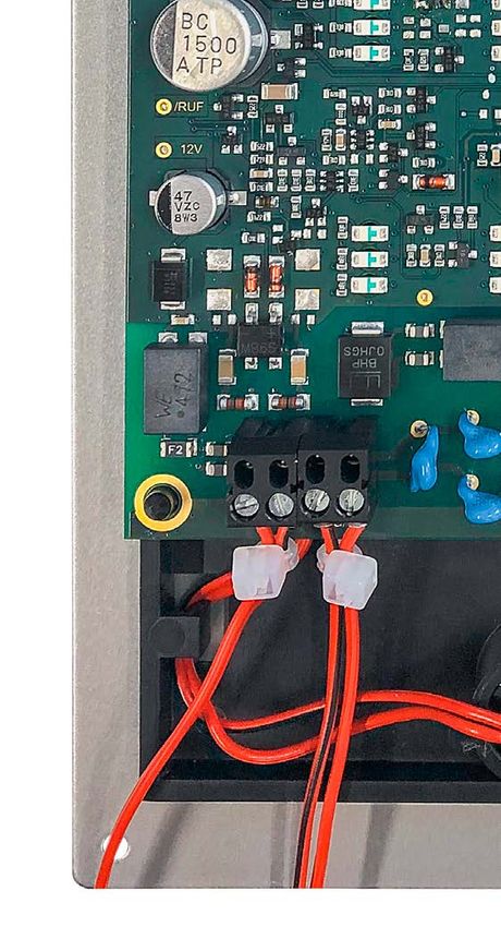
Anleitung Türstationen a / b Serie 5 / 10
D
Kontakt
Wichtige Hinweise
Bitte beachten Sie, dass Behnke Sprechstellen und Zubehörteile ausschließlich von ausgebilde-
ten Elektro-, Informations-, Telekommunikationsfachkräften unter Einhaltung der einschlägigen
Normen und Regeln installiert und gewartet werden dürfen. Achten Sie bitte darauf, dass die Geräte
vor Wartungs- oder Reparaturarbeiten vom Stromnetz (Steckernetzteil) und vom Netzwerk bzw.
Telefonanschluss getrennt sind und die einschlägigen Sicherheitsregeln eingehalten werden.
Weitere rechtliche Hinweise finden Sie auf Seite 18.
Kontakt
Info-Hotline Telecom Behnke GmbH
Ausführliche Informationen zu Produkten, Gewerbepark „An der Autobahn“
Projekten und unseren Dienstleistungen: Robert-Jungk-Straße 3
Tel.: +49 (0) 68 41 / 81 77-700 66459 Kirkel
24 h Service-Hotline E-Mail- und Internet-Adresse
Sie brauchen Hilfe? Wir sind 24 Stunden info@behnke-online.de
für Sie da und beraten Sie in allen tech- www.behnke-online.de
nischen Fragen und geben Starthilfen:
Tel.: +49 (0) 68 41 / 81 77-777
2 www.behnke-online.de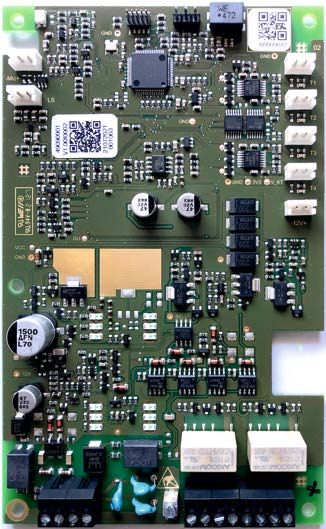
Anleitung Türstationen a / b Serie 5 / 10
                                                                                                                                              D
                                                                                                                            Inhalt

Inhalt
1. Einleitung4
  1.1. Allgemeines�����������������������������������������������������������������������������������������������������������������������4

2. Montage und Inbetriebnahme6
  2.1. Einbau Unterputzgehäuse������������������������������������������������������������������������������������������������ 6
  2.2. Serie 5 / 10 montieren������������������������������������������������������������������������������������������������������ 6
  2.3. Anschluss�������������������������������������������������������������������������������������������������������������������������7
  2.4. Beschriftungsfeld wechseln�������������������������������������������������������������������������������������������� 8

3. Anschluss9
  3.1. Anschlusspläne ��������������������������������������������������������������������������������������������������������������� 9

4. Konfiguration10

5. Bedienung14

6. FAQ15

7. Technische Daten17

8. Rechtliche Hinweise18

9. CE-Erklärung / EC-Declaration55

www.behnke-online.de                                                                                                                          3
Anleitung Türstationen a / b Serie 5 / 10
D
Einleitung
1. Einleitung
1.1. Allgemeines Dichtungen
Zum Schutz vor Feuchtigkeit achten Sie bitte
Bitte beachten Sie bei der Installation und Konfi- beim Einbau Ihrer Türstation auf den korrekten
guration Ihrer Türstation folgende Eigenschaften: Sitz der mitgelieferten Dichtungen. Die Dichtung
▸ Betrieb an einer analogen Nebenstelle einer muss sauber auf dem Rahmen des Unter- oder
Telefonanlage oder sonstigen a / b-Schnitt- Aufputzgehäuses aufliegen! Unterputzgehäuse
stellen. Hinweis: Bitte achten Sie beim sind zum Einbau in Mauerwerk. Sie finden darin
Einsatz sonstiger a / b-Schnittstellen darauf, die wichtigsten Einbauhinweise eingeklebt.
dass sie die entsprechenden Vorgaben einer
analogen Nebenstellen, wie Besetztton, MFV- Reinigung und Pflege
Transparenz etc. erfüllen. Sie haben hochwertige Behnke Produkte mit
▸ Betrieb ohne zusätzliche Spannungsver Frontblenden aus verschiedenen Materialien
sorgung möglich verbaut. Für alle Materialien gilt, dass diese in
▸ Die Türstationen arbeiten im Vollduplexmodus. regelmäßigen ausreichend kleinen Abständen,
dem Material entsprechend, mit einem passen-
Einbaubedingungen den Reinigungsmittel zu reinigen sind. Somit
▸ Die optimale Einbauhöhe liegt vor, wenn die wird eine vorzeitige Alterung und sonstige
Bedienung der Türstation mit einem Abstand Patina Bildung auf den Oberflächen verhindert.
von 30-50 cm gewährleistet ist und der Nutzer Die passenden Pflegehinweise zu den von
bequem waagerecht direkt in das Mikrofon Behnke gelieferten Oberflächen finden Sie auf
sprechen kann. unserer Homepage unter:
www.behnke-online.de/downloads/
Montage im Außenbereich pflegehinweise
▸ Dichten Sie bei der Unterputzmontage den
oberen Rand der Türstation zum Schutz gegen Original Behnke Teile
Regenwasser gut ab, insbesondere bei einem Setzen Sie bitte ausschließlich Behnke Teile als
unebenen Untergrund (z.B. mit Silikon). Beim Zubehör oder Ersatzteil ein – dies gilt auch für
Einsatz von Abdeckblenden ist die Abdeck- Steckernetzteile! Nur so ist ein störungsfreier
blende mit einer passenden Dichtmasse Betrieb gewährleistet. Elektroniken nur in den
gegen das Unterputzgehäuse bzw. die plane gelieferten Gehäusen einbauen bzw. verbauen.
Fläche bei Hohlwandmontagen abzudichten. Bei der Montage in Fremdgehäusen oder ohne
▸ Bei Einbau in Fremdstelen muss durch geeig- die gelieferten Gehäuse keine Gewährleistung
nete Maßnahmen die Kondensatbildung in auf Funktion und Zulassung.
der Stele verhindert werden.
4 www.behnke-online.deAnleitung Türstationen a / b Serie 5 / 10
D
Einleitung
Konfiguration
Die Türstationen wird aus der Ferne per Telefon
(MFV-/DTMF-Signal = Tonwahl) konfiguriert. Alle
Türstationen werden bereits vorkonfiguriert mit
einer Standardkonfiguration ausgeliefert.
Vorschriften
Bitte beachten Sie die einschlägigen Vorschrif-
ten für die Installation von Fernmelde-und
Elektroanlagen!
www.behnke-online.de 5Anleitung Türstationen a / b Serie 5 / 10
D
Montage und Inbetriebnahme
2. Montage und Inbetriebnahme
2.1. Einbau Unterputzgehäuse 2.2. Serie 5 / 10 montieren
Bitte beachten Sie die Montagehinweise im Türstationen der Serien 5 /10 werden bereits
UP-Gehäuse. montiert geliefert. Gehen Sie bitte beim Einbau
wie hier gezeigt vor. Hinweise zur elektrischen
Montage finden Sie auf den folgenden Seiten.
Edelstahlstreifen abklipsen (nur bei Serie 10)
Edelstahlstreifen entfernen (nur bei Serie 10)
Türstation anschließen und im vorgesehen
AP/UP-Gehäuse, Hohlwand oder in der Behnke
säule (nur Serie 5) befestigen. Bei Geräten der
Serie 10 die Edelstahlstreifen wieder befestigen.
6 www.behnke-online.deAnleitung Türstationen a / b Serie 5 / 10
D
Montage und Inbetriebnahme
2.3. Anschluss
Zur Inbetriebnahme muss die Behnke Türstation
Serie 5/10 an eine analoge Nebenstelle einer zur potentialfreien
Telefonanlage oder einer a/b-Schnittstelle 12-15V= Spannung
Behnke Steckernetzteil
angeschlossen werden. Dabei wird die zweiad- 20-9585
rige Telefonleitung zur Behnke Türstation Serie
zur analogen Neben-
5/10 geführt und an der dafür vorgesehenen stelleder TK-Anlage, zur
a/b-Schnittstelle
Anschlussklemme angeschlossen.
Hinweis: Mehrere Behnke Türstationen dürfen Abstand zwischen
Schraubklemmen und
nicht parallel an einer a/b-Leitung betrieben Kabebinder (im Lieferum-
fang) max. 5 mm
werden.
Sie können darüber hinaus eine 12-15 V poten-
tialfreie Gleichspannung als Zusatzversorgung
an die Anschlussklemme „Zusatzversorgung“
(12 V ▸ Polarität beachten) anschließen. Diese
wird u. a. benötigt, um die Beleuchtung zu
betreiben (potentialfrei; nur Behnke Stecker-
netzteil 20-9585 verwenden). Ist erforderlich für
Beleuchtung, nicht erforderlich für Telefonbetrieb Abstand max. 5 mm
inkl. aller Funktionen.
Hinweis: Es dürfen nicht mehrere Geräte parallel
mit einem Netzteil betrieben werden.
Hinweis: Beachten Sie beim Anschluss
der Telefonleitung bzw. Zusatzversorgung
die Position der beiden Kabelbinder (im
Lieferumfang enthalten)
www.behnke-online.de 7Anleitung Türstationen a / b Serie 5 / 10
D
Montage und Inbetriebnahme
2.4. Beschriftungsfeld wechseln
Beschriftungsfeld vorsichtig mit Hilfe eines
Schraubendrehers aus der Türstation hebeln.
Vorlage zur Beschriftung unter
www.behnke-online.de/beschriftung
Nutzen Sie zur Beschriftung den beiliegenden
Bogen. Den beschrifteten Papierstreifen in das
Beschriftungsfeld einschieben.
Beschriftungsfeld in die Öffnung der Türstation
eindrücken – fertig.
8 www.behnke-online.deAnleitung Türstationen a / b Serie 5 / 10
D
Anschluss
3. Anschluss
3.1. Anschlusspläne
Serie 5/10
Anschlüsse
vorverdrahtet,
Anschlüsse
nicht entfernen!
vorverdrahtet,
nicht entfernen!
(Bei Serie 5/10
Anschlüsse T3/
T4/-12V+ nicht
benutzt)
Erde
12-15V= +
–
Potenzialfreie 12-15V= Spannung
max. 1A, max. 30VDC/VAC
max. 1A, max. 30VDC/VAC
Arbeitskontakte Relais 2
Arbeitskontakte Relais 1
Behnke Netzeil 20-9585
Relaisschaltleistung:
Relaisschaltleistung:
a Ader
b Ader
Analoge Nebenstelle einer
TK-Anlage, a/b Schnittstelle
www.behnke-online.de 9Anleitung Türstationen a / b Serie 5 / 10
D
Konfiguration
4. Konfiguration
Die Konfiguration dieser Behnke Sprechstellen Konfigurationsmodus beenden:
erfolgt immer von „Ferne“ mit einem Telefon (per Taste * kurz drücken oder die Verbindung durch
MFV-/DTMF-Signal = Tonwahl). Dazu rufen Sie die Auflegen trennen
Behnke Sprechstelle mit ihrer Nebenstellenruf-
nummer an. Um in den Konfigurationsmodus zu Quittierungstöne:
gelangen, muss ein 4-stelliger Sicherheitscode [Quittierungstöne:
eingegeben werden. Die Konfiguration selbst [Piep] = Bestätigung Konfiguration beendet
erfolgt durch die Eingabe von so genannten Kon- [Piep] [Piep] = Konfigurationsschritt eingegeben
figurationsschritten, die jeweils eine bestimmte [Piep] [Piep] [Piep] = Bestätigung einer Eingabe
Funktion einstellen. [PiepPiep] [PiepPiep] [PiepPiep] [PiepPiep] =
Falsche Eingabe
Konfiguration mit tonwahlfähigem Telefon
▸ Türstation anrufen Konfigurationsbeispiele der Sprechstelle:
▸ Türstation hebt ab und meldet sich mit drei Sprechstelle mit ihrer Nebenstellennummer
Pieptönen (für die Zeit der Verbindungsdauer anrufen
besteht die Möglichkeit den Konfigruationsmo- Sprechstelle meldet sich
dus zu starten) **0000 (Sicherheitscode im Auslieferungs
▸ Taste * nach dem Piepton zweimal drücken. zustand)
[Piep] (Eingabe von ** zum Start der Konfigura- 10 Code zum Türöffnen #
tion muss binnen 2 s erfolgen) 21 Rufnummer die bei Tastendruck von Taste 1
▸ Sicherheitscode eingeben (Vorgabe: 0 0 0 0) gewählt werden soll #
[Piep] [Piep] (Eingabe des Sicherheitscode muss 22 Rufnummer die bei Tastendruck von Taste 2
binnen 5 s nach Bestätigung der Eingabe ** gewählt werden soll #
erfolgen) * Konfiguration beenden
Konfigurationsschritte eingeben (Eingabe eines
Konfigurationswertes inkl. Bestätigung muss
binnen 15 s nach Aufruf des Konfigurationsschrit-
tes erfolgen. Bei Inaktivität wird der Konfigurations
modus nach 60 s automatisch beendet und die
eingestellten Werte werden gespeichert):
▸ Konfigurationscode eingeben (siehe Tabelle der
Konfigurationsschritte)
[Piep] [Piep]
▸ Parameter eingeben und mit Taste # abschließen
[Piep] [Piep] [Piep]
10 www.behnke-online.deAnleitung Türstationen a / b Serie 5 / 10
D
Konfiguration
Code Parameter Bestätigung
Reset und Auslieferungszustand herstellen:
00 **** #
Sicherheitscode ändern: Vorgabe: 0 0 0 0
01 neuer Code [Piep] neuer Code #
Anrufannahme des Türrufs am Telefon: Vorgabe: 1
03 0 = automatisch mit manueller Bestätigung per DTMF-Signal 0-9 (siehe #
dazu Konfigurationsschritt 9910)
1 = automatisch #
Verbindungsdauer: Vorgabe: 3
05 0 = unbegrenzt (d.h. begrenzt auf ca. 8 Stunden) #
1 = auf 1 Minute begrenzt #
…
…
9 = auf 9 Minuten begrenzt #
06 Lautstärke: Vorgabe: 3
1 = leise #
…
…
5 = laut #
Betriebsart Relais 1: Vorgabe: 00
08 00 = Relais schaltet bei Codeeingabe (Konfigurationsschritt 10) für die #
Aktivierungsdauer (Konfigurationsschritt 09)
01 = Relais 1 schaltet während der Betätigungsdauer Taste 1 #
02 = Relais 1 schaltet während der Betätigungsdauer Taste 2 #
03 = Relais 1 schaltet während der Betätigungsdauer Taste 1 und Taste 2 #
Aktivierungsdauer Relais 1: Vorgabe: 5
09 01 = 1 Sekunde #
02 = 2 Sekunden #
…
…
90 = 90 Sekunden #
www.behnke-online.de 11Anleitung Türstationen a / b Serie 5 / 10
D
Konfiguration
Code Parameter Bestätigung
Aktivierungscode Relais 1: Vorgabe: 0
10 1. Aktivierungscode #
Der Aktivierungscode besteht nur aus Ziffern u. ist maximal vierstellig.
Relaiskativierung erfolgt bei bestehender Sprachverbindung per
MFV / DTMF mit Code #
Betriebsart Relais 2: Vorgabe: 30
12 00 = Relais 2 deaktivieren #
01 = Relais 2 schaltet während der Betätigungsdauer Taste 1 #
02 = Relais 2 schaltet während der Betätigungsdauer Taste 2 #
03 = Relais 2 schaltet während der Betätigungsdauer Taste 1 und Taste 2 #
30 = Relais schaltet bei Rufauslösung während der abgehenden #
Verbindung für die Zeit der Verbindung ab Tastendruck
Rufnummer konfigurieren:
21 Rufnummer Rufnummer 1 (Taste 1) #
22 Rufnummer Rufnummer 2 (Taste 2) #
Die Rufnummern bestehen nur aus Ziffern und sind maximal 20-stellig.
Bei der Eingabe der Rufnummern sind folgende Sondersymbole zulässig:
*0 = * wählen
*1 = # wählen
*2 = 2 Sekunden Pause
Beleuchtung Beschriftungsfeld: Vorgabe: 0
73 0 = deaktiviert #
1 = dunkel #
…
…
5 = hell #
Aktiviert bzw. deaktiviert die Beleuchtung der Beschriftungsfelder. Für die
Aktivierung ist ein 12-15V= Steckernetzteil erforderlich.
12 www.behnke-online.deAnleitung Türstationen a / b Serie 5 / 10
D
Konfiguration
Code Parameter Bestätigung
Verstärkung Mikrofonsignal: Vorgabe: 3
912 1 = unempfindlich #
…
…
4 = empfindlich #
Relaisaktivierungston: Vorgabe: 1
950 0 = inaktiv #
1 = aktiv #
9910 Timeout warten auf Abheben durch Gegenstelle und Bestätigung durch
DTMF-Ton: (siehe dazu auch Konfigurationsschritt 03. Nur aktiv wenn
Konfigurationsschritt 03 = 0) Vorgabe 60
01 = 01 Sekunde #
02 = 02 Sekunde #
…
…
99 = 99 Sekunden #
www.behnke-online.de 13Anleitung Türstationen a / b Serie 5 / 10
D
Bedienung
5. Bedienung
Funktionen an der Türstation (= außen)
Anrufen per Ruftaste
▸ Eine der Ruftasten drücken
▸ Die für die Taste einprogrammierte Rufnummer wird gewählt.
▸ Bei Rufannahme wird eine Sprachverbindung aufgebaut; Verbindung wird automatisch wieder been-
det (auf erkannten Besetzton hin).
Funktionen am Telefon (= innen):
Rufannahme – Sprachverbindung bei Anruf von der Tür
▸ Je nach verwendeter Telefonanlage und Telefonapparat kann in Ihrem Display die Nummer der
Türstation oder eine Textinformation wie z.B. „Türstation“ angezeigt werden (Leistungsmerkmal der
TK-Anlage).
▸ Anruf von der Tür wie einen normalen Telefonanruf entgegennehmen.
▸ Sprachverbindung durch Auflegen beenden.
Türöffnen von innen
▸ Anruf von der Tür wie einen normalen Telefonanruf entgegennehmen.
▸ Codeziffer eingeben (Standard 0)
▸ drücken – der Türöffner wird ausgelöst.
Systemtelefone von Siemens, Alcatel, Tenovis oder anderen Herstellern auf „MFV-Nachwahl“ ein-
stellen = Tonwahl (erforderlich für Türöffnerfunktion u.a.)!
14 www.behnke-online.deAnleitung Türstationen a / b Serie 5 / 10
D
FAQ
6. FAQ
Tür wählt keine oder falsche Rufnummer
▸ Rufnummer nicht konfiguriert
▸ Falsche Rufnummer konfiguriert
▸ Türstation hat Konfiguration nicht angenommen siehe: Türstation lässt sich nicht konfigurieren
▸ Gegenstelle im Haus läutet einmal, keine Sprachverbindung *2 (2 Sekunden Pause) vor und hinter
die Rufnummer konfigurieren
Türsprechstelle lässt sich aus der Ferne nicht konfigurieren
▸ Das Telefon mit dem Sie die Türstation konfigurieren sendet keine MFV / DTMF-Töne Telefon mit
MFV / DTMF-Wahl benutzen
▸ Korrekt in den Konfigurationsmodus mit **0000 einsteigen
Keine (direkte) Sprachverbindung nach Verbindungsaufbau
▸ a / b-Port prüfen Port in der TK-Anlage muss als Telefonport generiert sein, nicht als TFE/Türsprech-
stelle/FTZ
Nach Verbindungsende kein Besetztton
▸ a / b-Port prüfen, es wird kein Besetzton ausgegeben, zum Gesprächsende muss ein Besetzton durch
die Telefonanlage ausgegeben werden. Telefonanlage muss zum Verbindungsende einen Besetzton
ausgeben.
Namensschild nicht beleuchtet
▸ Spannungsversorgung fehlt
▸ Spannungsversorgung ist verpolt
▸ Konfigurationsschritt 73 im Auslieferungszustand deaktiviert aktivieren
Türöffner wird nicht angesteuert
▸ Anschluss des Türöffners prüfen korrekte Schließerkontakte verwenden
▸ Spannungsversorgung für Türöffner fehlt
bauseits (nicht mit Behnke Spannungsversorgung parallel schalten)
▸ Telefon sendet keine MFV / DTMF-Töne -> siehe: Türstation lässt sich nicht konfigurieren
▸ Code zur Türöffnung nicht oder falsch konfiguriert (Auslieferungszustand 0#)
▸ Codeeingabe mit # betätigen
www.behnke-online.de 15Anleitung Türstationen a / b Serie 5 / 10
D
FAQ
Türsprechstelle ohne Funktion
▸ a / b-Port prüfen ggf. messen
▸ Falls Zusatzversorgung angeschlossen, prüfen ob diese potentialfrei ist
▸ Mehrere Türstationen parallel angeschlossen jedes Telefon benötigt eigenen analogen Anschluss
und eigene potentialfreie Spannungsversorgung
▸ Schleifenstrom der TK-Anlage ausreichend
muss größer als 20 mA sein
Siehe: technische Daten Türstation
Sporadische Rufauslösung bei Türsprechstellen
▸ Zusätzliche Ruftasten angeschlossen, Taster entfernen, keine Taster parallel schalten
▸ Fremdtaster angeschlossen, Taster auf Tauglichkeit überprüfen, prellen,Potentialfreiheit, keine
gemeinsame Masse.
Konfigurationswert (z.B. Rufnummer) löschen
▸ Konfigurationsmodus starten
▸ Konfigurationsschritt aufrufen und mit # bestätigen. Der eingestellte Konfigurationswert ist
gelöscht.
16 www.behnke-online.deAnleitung Türstationen a / b Serie 5 / 10
D
Technische Daten
7. Technische Daten
Anschlussart: analoge Nebenstelle, a / b-Schnittstelle
Energieversorgung: über die a / b-Schnittstelle
Schleifenspannung: 20-70 VDC
Schleifenstrom: 20-60 mA
Zusatzversorgung: 12-15 V= potentialfrei
Behnke Steckernetzteil oder andere Zusatzversorgung in Verbin-
dung mit Behnke DC / DC-Wandler; pro Steckernetzteil eine Behnke
Türstation möglich
Abschluss: Zr nach TBR 21
Erkanntes Rufsignal: nicht genau spezifizierbar, da abhängig von Amplitude, Frequenz
und Dauer des Rufsignals
Erkanntes Besetztsignal: 400-450 Hz sinus
Erkannte Besetztsignaldauer: Signale mit 160-700 ms Ton bzw. 160-700 ms Pause
Zulässige Kabellänge: Behnke Türstation ist vormontiert. Keine Verlängerung der Anschluss-
leitungen zu Lautsprecher, Mikrofon und Tasten vorgesehen.
Wahlverfahren: MFV, 50/50 ms (Ton/Pause)
Eingebaute Relais: 2 Stück (2 Schaltrelais)
Relaisschaltleistung: max. 1 A, max 30 VDC/VAC
Speicher: EEprom, nicht flüchtig
Betriebstemperatur: -20° bis +50°
Geprüft nach: EN 55032, EN 55035 (Elektromagnetische Verträglichkeit)
EN 62368-1 (Elektronische Sicherheit)
www.behnke-online.de 17Anleitung Türstationen a / b Serie 5 / 10
D
Rechtliche Hinweise
8. Rechtliche Hinweise
1. Änderungen an unseren Produkten, die dem Infos zum Produkthaftungsgesetz:
technischen Fortschritt dienen, behalten wir
uns vor. Die abgebildeten Produkte können im 1. Alle Produkte aus dieser Anleitung dürfen nur
Zuge der ständigen Weiterentwicklung auch für den angegebenen Zweck verwendet werden.
optisch von den ausgelieferten Produkten Wenn Zweifel bestehen, muss dies mit einem
abweichen. kompetenten Fachmann oder unserer Service-
abteilung (siehe Hotline-Nummern) abgeklärt
2. Abdrucke oder Übernahme von Texten, Ab- werden.
bildungen und Fotos in beliebigen Medien aus
dieser Anleitung – auch auszugsweise – sind 2. Produkte, die spannungsversorgt sind (insbe-
nur mit unserer ausdrücklichen schriftlichen sondere 230 V-Netzspannung), müssen vor dem
Genehmigung gestattet. Öffnen oder Anschließen von Leitungen von der
Spannungsversorgung getrennt sein.
3. Die Gestaltung dieser Anleitung unterliegt
dem Urheberschutz. Für eventuelle Irrtümer, 3. Schäden und Folgeschäden, die durch Ein-
sowie inhaltliche bzw. Druckfehler (auch bei griffe oder Änderungen an unseren Produkten
technischen Daten oder innerhalb von Grafiken sowie unsachgemäßer Behandlung verursacht
und technischen Skizzen) übernehmen werden, sind von der Haftung ausgeschlossen.
wir keine Haftung. Gleiches gilt für eine unsachgemäße Lagerung
oder Fremdeinwirkungen.
4. Beim Umgang mit 230 V-Netzspannung oder
mit am Netz oder mit Batterie betriebenen
Produkten, sind die einschlägigen Richtlinien
zu beachten, z. B. Richtlinien zur Einhaltung
der elektromagnetischen Verträglichkeit oder
Niederspannungsrichtlinie. Entsprechende
Arbeiten sollten nur von einem Fachmann aus-
geführt werden, der damit vertraut ist.
5. Unsere Produkte entsprechen sämtlichen, in
Elektromagnetische Deutschland und der EU geltenden, techni-
Verträglichkeit schen Richtlinien und Telekommunikations-
Niederspannungsrichtlinie bestimmungen.
18 www.behnke-online.deinstructionsVersion 1.1 D Türstationen a / b Serie 5 / 10 Seite ....... 3 GB Manual Door Intercom Devices a / b series 5 / 10 Page ......21 FR Portiers téléphoniques a / b Séries 5 / 10 Page ...... 39
Manual Door Intercom Devices a / b series 5 / 10
GB GB
            Contact

                   Important Information

        Please note that Behnke intercoms and accessories may only be installed and serviced by qualified
        electricians, IT and telecommunications technicians who comply with the corresponding norms and
        regulations. Before carrying out service and maintenance work, please ensure that the devices are
        safely disconnected from the power grid (unplug power supply unit) and are disconnected from any
        other network and that all relevant safety regulations will be maintained.

        For further legal information, please see page 36.

        contact
             Information:                                      Telecom Behnke GmbH
             For detailed information on our product,          Gewerbepark „An der Autobahn“
             projects and services:                            Robert-Jungk-Straße 3
             Phone: +49 (0) 68 41/81 77-700                    D-66459 Kirkel

             24-hour service:                                  E-mail address and website
             Do you need help? Feel free to contact us         info@behnke-online.de
             24/7. We will be happy to assist you with         www.behnke-online.de
             any technical questions you may have and
             we will also help you getting set-up.
             Phone: +49 (0) 68 41/81 77-777

  20                                                                             www.behnke-online.com
Manual Door Intercom Devices a / b series 5 / 10
GB
Contents
Contents
1. Introduction22
1.1. General Information����������������������������������������������������������������������������������������������������������22
2. Mounting and set-up24
2.1. Installation flush-mounted housing����������������������������������������������������������������������������������24
2.2. Serie 5/10 assembly���������������������������������������������������������������������������������������������������������24
2.3. Connection���������������������������������������������������������������������������������������������������������������������� 25
2.4. Change labels������������������������������������������������������������������������������������������������������������������26
3. Connection27
3.1. Wiring diagrams ��������������������������������������������������������������������������������������������������������������27
4. Configurations and Set-up28
5. Operation32
6. FAQ33
7. Specifications35
8. Legal Information36
9. CE-Erklärung / EC-Declaration55
www.behnke-online.com 21Manual Door Intercom Devices a / b series 5 / 10
GB GB
Introduction
1. Introduction
1.1. General Information Sealings
To protect your device from any dampness,
Please note the following features when install- please make sure the included sealings have
ing and setting up your Behnke door intercom been put in place correctly upon installation of
device: your door intercom station. The sealing must
▸ Operation with an analogue extension to a be correctly placed onto the frame of the in-wall
telephone system, or other a / b ports.Note: housing or the on-wall housing! In-wall housings
When using other a / b ports, please make are available for installation in masonry. You will
sure that you fulfil the corresponding require- find the most important mounting information on
ments of an analogue extension, such as busy a sticker inside the respective housing.
tone, DTMF transparency, etc.
▸ Operation possible without additional power Maintenance and Care
supply You have chosen high-quality Behnke products
▸ The door intercom stations work in full-duplex with front panels made from various materials.
mode. Regardless of the material, all front panels
require regular cleaning in sufficiently short inter-
Installation requirements vals using a cleansing agent appropriate for the
▸ The perfect installation height for your device material in question. This prevents early ageing
is a position that enables operating the door and patina formation on the surface. You can find
intercom at a distance of 30-50 cm so the user the corresponding care instructions for surfaces
can easily and horizontally speak directly into delivered by Behnke on our homepage:
the microphone. www.behnke-online.de/downloads/pflege
hinweise
Outside mounting
▸ All in-wall mounted door intercom devices Original Behnke components
need to be well sealed against rain water Please do not use any other parts but original
entering into the housing, esp. with an Behnke components or spare parts – this also
uneven underground (e.g. using silicone). applies to plug-in power supply units! This will
When using cover panels, the cover panel guarantee an intercom operation free from inter-
needs to be sealed with a suitable sealing ference. Please mount and install the electronics
agent against the in-wall housing or the level only in the provided housings. If a third-party
surface for cavity wall mounting. housing or a housing other than the one pro-
▸ For mounting in steles by third-party provid- vided for mounting is used, we cannot guarantee
ers, appropriate action needs to be taken to functioning and approval of your door intercom.
prevent condensation water from forming
inside the stele.
22 www.behnke-online.comManual Door Intercom Devices a / b series 5 / 10
GB
Introduction
Configuration
The door intercom devices are set up remotely
via telephone (DMTF signal = tone dial). All door
intercom devices are delivered with a standard
pre-configuration.
Prescriptions
Please adhere to the relevant prescriptions for
the installation of communications and elec-
tronic systems!
www.behnke-online.com 23Manual Door Intercom Devices a / b series 5 / 10
GB GB
Mounting and set-up
2. Mounting and set-up
2.1. Installation flush-mounted housing 2.2. Serie 5/10 assembly
Please follow the installation instructions in the The intercom station of the series 5/10 is
flush-mounted housing. delivered already assembled. To mount these
door intercom devices, please follow the steps
shown here. For advice on electric mounting,
please see the following pages.
Unclip the stainless steel strip
Remove the stainless steel strip
Connect the Intercom station and attach it
in the provided on-wall/flush mounting hous-
ing, cavity or Behnke column (series 5 only).
Re-attach the stainless steel strips in Series 10
devices.
24 www.behnke-online.comManual Door Intercom Devices a / b series 5 / 10
GB
Mounting and set-up
2.3. Connection
For commissioning, please connect your Behnke
Series 5/10 intercom station to an analogue for the potential-free
extension of a telephone system or an a/b 12-15V= voltage,
Behnke power supply unit
port. To do so, please connect the two-core 20-9585
telephone line to the Behnke Intercom using the
to the analogue
designated screw terminals. extension of the telephone
system, to the a/b port
Note: Multiple Behnke door intercom devices
must not be operated in parallel via an a/b line. Distance between screw
terminals and cable ties
(included in the box) is
5mm max.
You may also connect an additional 12-15V
potential-free DC power supply to the screw ter-
minal “additional power supply” (note the 12V
▸ polarity) as an additional power supply. This
is required, among other things, to operate the
illumination (potential-free; use only Behnke
power supply unit 20-9585). Required for
lighting, not required for telephone operation
including all functions.
Distance 5mm max.
Note: The concurrent operation of multiple
devices using one power supply unit is not
permitted.
Note: When connecting the telephone
line or additional power supply, note
the position of the two cable ties
(included in the box)
www.behnke-online.com 25Manual Door Intercom Devices a / b series 5 / 10
GB GB
Mounting and set-up
2.4. Change labels
Use a screwdriver to carefully remove the label-
ling unit from the intercom station.
Labelling template available at
www.behnke-online.de/beschriftung
Use the provided labelling sheet for your labels.
Enter the labelled paper strip into the labelling
unit.
Press the labelling unit back into the intercom
station – done.
26 www.behnke-online.comManual Door Intercom Devices a / b series 5 / 10
GB
Connection
3. Connection
3.1. Wiring diagrams
5/10 Series
Connections are
prewired,
Connections are
do not remove!
prewired,
do not remove!
(For series 5/10,
the T3/T4/-12V+
connections are
not used)
Grounding
12-15V= +
–
Operating contact for relay 2
Operating contact for relay 1
Potential-free 12-15V= voltage,
max. 1A, max. 30VDC/VAC
max. 1A, max. 30VDC/VAC
Behnke power supply unit 20-9585
Relay switch power:
Relay switch power:
Wire a
Wire b
Analogue extension of a
telephone system, a/b port
www.behnke-online.com 27Manual Door Intercom Devices a / b series 5 / 10
GB GB
Configurations and Set-up
4. Configurations and Set-up
Behnke door intercom devices are always set up Exit set-up mode:
remotely via telephone (via DTMF signal = tone Shortly press the * key or end the connection by
dial). Call your Behnke door intercom using the hanging up
analogue extension number. To enter set-up
mode, you need to enter a 4-digit Acknowledgement tones:
security code. The different settings are changed [beep] = Confirmation of finished configuration
via configuration step codes with an individual [beep] [beep] = Configuration step entered
code for each function to be set. [beep] [beep] [beep] = Confirmation of an input
Set-up using a telephone with DTMF dialling Set-up examples for the door intercom:
▸ Call your door intercom Call the door intercom using your analogue
▸ Door intercom answers with three beeps (it is extension number
possible to start the configuration mode for the Door intercom answers the call
duration of the connection) **0000 (default safety code)
▸ Press the * key twice after the beep sound. 10 Code to open the door #
[Beep] (** must be entered within 2 s to start 21 Telephone number that should be dialed
the configuration) when pressing the 1 key #
▸ Enter the security code (default: 0 0 0 0) 22 Telephone number that should be dialed
[beep] [beep] (The security code must be when pressing the 2 key #
entered within 5 s after confirming the ** * Exit Set-Up
input)
Enter configuration steps (Enter a configuration
value incl. confirmation within 15 s after access-
ing the configuration step. In case of inactivity,
the configuration mode is automatically termi-
nated after 60 s and the set values are saved):
▸ Enter the configuration step code (cf. table
page)
[beep ] [beep]
▸ Enter the desired parameter and confirm with
the # key
[beep] [beep] [beep]
28 www.behnke-online.comManual Door Intercom Devices a / b series 5 / 10
GB
Configurations and Set-up
Code Parameter Confirmation
Reset and restore default settings:
00 **** #
Change security code: Default: 0 0 0 0
01 new code [beep] new code #
Answering the telephone call when the doorbell was rung: Default: 1
03 0 = automatically with manual confirmation via DTMF signal 0-9 (cf. Con- #
figuration step 9910)
1 = automatically #
Connection interval: Default: 3
05 0 = unlimited (i.e. limited to approx. 8 hours) #
1 = limited to 1 minute #
…
…
9 = limited to 9 minutes #
06 Volume: Default: 3
1 = soft #
…
…
5 = loud #
Operations modes Relay 1: Default: 00
08 00 = Relay is switched when entering the code (Configuration step 10) for #
the activation time (Configuration step 09)
01 = Relay 1 is switched while button 1 is pressed #
02 = Relay 1 is switched while button 2 is pressed #
03 = Relay 1 is switched while button 1 and button 2 are pressed #
Relay 1 activation time: Default: 5
09 01 = 1 second #
02 = 2 seconds #
…
…
90 = 90 seconds #
www.behnke-online.com 29Manual Door Intercom Devices a / b series 5 / 10
GB GB
Configurations and Set-up
Code Parameter Confirmation
Relay 1 activation time: Default: 0
10 1. Activation code #
The activation code consists of digits only and may be up to 4 digits long.
The relay is activated through voice connection via
DTMF with code #
Operations modes Relay 2: Default: 30
12 00 = Deactivate relay 2 #
01 = Relay 2 is switched while button 1 is pressed #
02 = Relay 2 is switched while button 2 is pressed #
03 = Relay 2 is switched while button 1 and button 2 are pressed #
30 = The relay is switched at call activation during an outgoing #
call for the duration of the call after pressing the button
Telephone number configuration:
21 Telephone numbertelephone number 1 (button 1) #
22 Telephone numbertelephone number 2 (button 2) #
Telephone numbers consist of digits only and may be up to 20 digits long.
When entering a telephone number, you may use the following special
characters:
*0 = dial *
*1 = dial #
*2 = pause for 2 seconds
Label illumination: Default: 0
73 0 = disabled #
1 = dark #
…
…
5 = bright #
Use this step to turn label illumination on/off. Requires an additional
12-15V power supply unit.
30 www.behnke-online.comManual Door Intercom Devices a / b series 5 / 10
GB
Configurations and Set-up
Code Parameter Confirmation
Microphone signal amplification: Default: 3
912 1 = Not sensitive #
…
…
4 = Sensitive #
Relay activation tone: Default: 1
950 0 = disabled #
1 = enabled #
9910 Timeout, waiting for the remote station to accept the call and confirma-
tion via DTMF tone: (Cf. Configuration step 03. Only active if configuration
step 03 = 0) Default: 60
01 = 01 second #
02 = 02 seconds #
…
…
99 = 99 seconds #
www.behnke-online.com 31Manual Door Intercom Devices a / b series 5 / 10
GB GB
Operation
5. Operation
Door intercom device functions (= outside)
Calling via call button
▸ Press one of the call buttons
▸ The pre-programmed telephone number for this button will be dialled.
▸ If the call is answered, a voice call is established; the call is automatically terminated (after recog-
nising the busy tone).
Functions on the telephone (= inside):
Answering calls – Voice call when door is calling
▸ Depending on the telephone system and telephone used, the number of the door intercom device
or a text information, such as “door intercom device” can be shown on your display (telephone
system feature).
▸ Answer the call from the door like a normal phone call.
▸ The voice call will be terminated by hanging up.
Open the front door from the inside
▸ Answer the call from the door like a normal phone call.
▸ Enter the code number (standard setting 0)
▸ press – the door opener is triggered.
Set system telephones from Siemens, Alcatel, Tenovis or other manufacturers to “DTMF dialling” =
tone dial (required for the door opening function, etc.)!
32 www.behnke-online.comManual Door Intercom Devices a / b series 5 / 10
GB
FAQ
6. FAQ
Door dials no or wrong telephone number
▸ Telephone number not configured
▸ Wrong telephone number configured
▸ Door intercom device has not accepted the set-up, cf.: Door intercom device cannot be configured
▸ Remote station in the house rings once, no voice call *2 (pause for 2 seconds) configure before
and after the telephone number
Door intercom device cannot be configured remotely
▸ The telephone with which you are configuring the door intercom device does not send any DTMF
tones Use telephone with DTMF tone
▸ Correctly enter the set-up mode with **0000
No (direct) voice call after connection
▸ Check a / b port Port in the telephone system must be generated as telephone port, not as TFE/
door intercom device/FTZ
No busy tone after ending the call
▸ Check a / b port, there is no busy tone, but the telephone system must send a busy tone after the
end of the call. Telephone system must send a busy tone when ending the call.
Name plate not illuminated
▸ Power supply is missing
▸ Polarity of power supply is reversed
▸ Configuration step 73 is deactivated in the delivery state activate
Door opener is not triggered
▸ Check door opener connection Use correct closing contacts
▸ Power supply for door opener missing
on-site (do not connect in parallel to Behnke power supply)
▸ Telephone does not send DTMF tones -> cf.: Door intercom device cannot be configured
▸ Code for opening doors is not or wrongly configured (default setting 0#)
▸ Confirm code entry with #
www.behnke-online.com 33Manual Door Intercom Devices a / b series 5 / 10
GB GB
FAQ
Door intercom device without function
▸ Check a / b port, measure if necessary
▸ If additional power supply is connected, check if it is potential-free
▸ Multiple door intercom devices are connected in parallel each telephone requires its own ana-
logue connection and its own potential-free power supply
▸ Coil current of the telephone system is sufficient
must be more than 20mA
Cf: Technical Specifications of the door intercom device
Occasional call activation of door intercom devices
▸ Additional call buttons connected, remove buttons, do not connect buttons in parallel
▸ External button connected, check button for functionality, bounce, freedom from potentials, no
common mass.
Delete configuration value (e.g. telephone number)
▸ Start set-up mode
▸ Enter configuration step and confirm with # The set configuration value will be deleted.
34 www.behnke-online.comManual Door Intercom Devices a / b series 5 / 10
GB
Specifications
7. Specifications
Connection type: analogue extension, a / b port
Power supply: via the a / b port
Coil tension: 20-70 VDC
Coil current: 20-60 mA
Additional power supply: 12-15 V= potential-free
Behnke power supply unit or any other additional power supply
in connection with a Behnke DC-DC converter; one Behnke door
intercom device per power supply unit
Terminal: ZR according to TBR 21
Recognised caller signal: cannot be specified exactly, as it depends on the signal’s
amplitude, frequency and interval
Recognised busy signal: 400-450 Hz sinus
Recognised busy signal interval: Signal tones for 160-700 ms or pauses for 160-700 ms respectively
Permissible cable length: Behnke door station is pre-assembled. No extension of the
connection cables to the loudspeaker, microphone, and buttons
provided.
Dialling methods: DTMF dialling, 50/50 ms (tone/pause)
Built-in relays: 2 pcs. (2 switch relays)
Relay switch power: max. 1A, max. 30VDC/VAC
Memory: EEprom, non-volatile
Operating temperature range: -20 °C to +50 °C
Tested according to: EN 55032, EN 55035 (Elecromagnetic Compatibility)
EN 62368-1 (Electronic Safety)
www.behnke-online.com 35Manual Door Intercom Devices a / b series 5 / 10
GB GB
Legal Information
8. Legal Information
1. We reserve the right to change our products, Information with regard to product liability::
without notice, in line with technical progress.
As a result of continuous development, the 1. All products mentioned in these instructions
products illustrated may look different from the may only be used for the purpose intended. In
products actually delivered. case of doubts, please contact a competent
specialist or our services department (cf. tele-
2. Reprints or adoption of texts, images, and phone numbers).
pictures from these instructions in any media –
given in full or as extracts – require our express 2. Products with a power supply (especially
written consent. when mains-operated at 230 V) must be discon-
nected before opening or during installation.
3. Design and layout of these instructions are
copyright protected. We do not assume any 3. We are not liable for damages and conse-
liability for possible errors, contents errors, and quential damages due to modifications of or
misprints (including technical data or within changes to our products or due to improper
images and use. This also applies to improper storage or
technical diagrams). external influences.
4. Please observe the respective guidelines for
working with voltages of 230 V, mains-powered
or battery-powered products, e.g. directives for
complying with the electromagnetic compatibil-
ity or the Low Voltage Directive. Corresponding
work should only be performed by a trained
technician who has experience in this area.
5. Our products meet all technical guidelines
and telecommunications regulations currently
applicable in Germany and the EU.
Electromagnetic
Compatibility
Low Voltage Directive
36 www.behnke-online.commanuel
Version 1.1
D Türstationen a / b Serie 5 / 10 Seite ....... 3
GB Manual Door Intercom Devices a / b series 5 / 10 Page ...... 21
FR Portiers téléphoniques a / b Séries 5 / 10 Page ..... 39Manuel Portiers téléphoniques a / b Séries 5 / 10
F
Contact
Remarques importantes
Veuillez vous assurer que les dispositifs et accessoires Behnke ne sont installés et entretenus que
par des électriciens, informaticiens et techniciens réseau agréés et respectant les normes et régu-
lations en vigueur. Avant d’effectuer des travaux d’entretien ou de réparation, toujours débrancher
les appareils des réseaux électrique (bloc d’alimentation), informatique et téléphonique et respec-
ter les règles de sécurité en vigueur.
Vous trouverez des informations légales complémentaires sur la page 54.
contact
Hotline Telecom Behnke GmbH
Pour des informations détaillées concer- Gewerbepark „An der Autobahn“
nant nos produits, nos projets et nos Robert-Jungk-Straße 3
services : Tél. : +49 (0) 68 41/81 77-700 66459 Kirkel
Hotline SAV 24h/24 E-Mail et Internet
Vous avez besoin d’aide ? Nous sommes info@behnke-online.de
à votre service 24h/24 et vous proposons www.behnke-online.de
des conseils et solutions pour toutes vos
questions d’ordre technique, ainsi qu’une
aide à la mise en service :
Tél. : +49 (0) 68 41/81 77-777
38 www.behnke-online.frManuel Portiers téléphoniques a / b Séries 5 / 10
F
Sommaire
Sommaire
1. Introduction40
1.1. Généralités���������������������������������������������������������������������������������������������������������������������� 40
2. Montage et mise en service42
2.1. Installation du boîtier encastré�����������������������������������������������������������������������������������������42
2.2. Monter les séries 5 / 50����������������������������������������������������������������������������������������������������42
2.3. Raccordement������������������������������������������������������������������������������������������������������������������43
2.4. Changer le champ d’inscription����������������������������������������������������������������������������������������44
3. Raccordement45
3.1. Schéma de raccordement : �����������������������������������������������������������������������������������������������45
4. Configuration46
5. Utilisation50
6. FAQ51
7. Caractéristiques techniques53
8. Informations légales54
9. CE-Erklärung / EC-Declaration55
www.behnke-online.fr 39Manuel Portiers téléphoniques a / b Séries 5 / 10
F
Introduction
1. Introduction
1.1. Généralités ▸ Lors d’un montage sur des colonnes autres
que celles de Behnke, veuillez prendre les
Lors de l’installation et de la configuration de mesures nécessaires afin de vous assurer
votre portier téléphonique, veuillez respecter qu’il n’y aura pas de condensation dans la
les propriétés suivantes : colonne.
▸ Fonctionnement sur un poste annexe ana-
logique d’une installation téléphonique ou Joints d’étanchéité
d’autres ports a / b. Remarque : lorsque vous Pour protéger de l’humidité, assurez-vous
utilisez d’autres ports a / b, veuillez vous que les joints d’étanchéité fournis sont bien
assurer qu’ils répondent aux spécifications positionnés lors du montage du portier télé-
correspondantes d’un poste annexe analo- phonique. Le joint doit reposer proprement sur
gique, telles que la tonalité d’occupation, la le cadre du boîtier encastré ou en saillie ! Les
transparence DTMF, etc. boîtiers encastrables sont conçus pour un mon-
▸ Fonctionnement possible sans alimentation tage dans un mur. Les consignes de montage
supplémentaire les plus importantes sont collées à l’intérieur
▸ Les portiers téléphoniques fonctionnent en des boîtiers.
mode full-duplex.
Entretien et nettoyage
Conditions de montage Vous avez installé des produits Behnke de
▸ La hauteur de montage optimale est atteinte, haute qualité avec des plaques avant fabri-
lorsque la distance d’utilisation du portier quées à partir de différents matériaux. Pour
téléphonique est de 30-50 cm et que l’utili- tous les matériaux, il est nécessaire de procéder
sateur peut confortablement parler dans le à un nettoyage régulier, à intervalles suffisam-
microphone qui se trouve à sa hauteur. ment courts, en utilisant un produit nettoyant
adapté au matériaux. Ainsi, vous éviterez un
Montage en extérieur vieillissement précoce des surfaces et une
▸ Dans le cas d’un montage encastré, assu- formation de patine sur celles-ci. Vous trouverez
rez-vous que l’arête supérieure du portier les consignes d’entretien appropriées pour les
téléphonique est bien étanche contre la surfaces fournies par Behnke sur notre page
saleté et la pluie, en particulier lorsque le d’accueil à l’adresse suivante :
support est irrégulier (utilisez par ex. du www.behnke-online.de/downloads/
silicone). Lors de l’utilisation de caches ces pflegehinweise
derniers doivent être pressés contre le boîtier
encastrable ou contre la surface lors d’un
montage cloison creuse, et étanchéifié avec
un mastic.
40 www.behnke-online.frManuel Portiers téléphoniques a / b Séries 5 / 10
F
Introduction
Pièces originales Behnke
N’utilisez que des accessoires ou pièces de
rechange Behnke, ceci vaut également pour
les blocs d’alimentation ! Seulement dans ce
cas pouvons-nous garantir un fonctionnement
sans entrave. Ne montez et n’installez les
composants électroniques que dans les boîtiers
fournis. Lors du montage dans des boîtiers
autres que ceux fournis, le fonctionnement et
l’homologation ne sont plus garantis.
Configuration
Les portiers téléphoniques sont configurés
à distance par téléphone (signal multifré-
quences/DTMF = composition par tonalités).
Toutes les portiers téléphoniques sont livrées
pré-configurées avec une configuration stan-
dard.
Réglementation en vigueur
Veuillez respecter les réglementations en
vigueur pour l’installation des systèmes de télé-
communications et des systèmes électriques !
www.behnke-online.fr 41Manuel Portiers téléphoniques a / b Séries 5 / 10
F
Montage et mise en service
2. Montage et mise en service
2.1. Installation du boîtier encastré 2.2. Monter les séries 5 / 50
Veuillez respecter les instructions de montage Les portiers téléphoniques des séries 5 / 10
dans le boîtier pour encastrement. sont livrés déjà montés. Pour l’installation,
procédez en vous basant sur ce qui suit. Vous
trouverez des consignes pour le montage élec-
trique sur les pages suivantes.
Déclipser la bande en acier inoxydable
(seulement pour la série 10)
Retirer les bandes en acier inoxydable
(série 10 uniquement)
Connectez le portier téléphonique et fixez-le
dans le boîtier en saillie/encastré prévu, dans
un mur creux ou dans la colonne Behnke (série
5 uniquement). Sur les appareils de la série 10,
fixez à nouveau les bandes d’acier inoxydable.
42 www.behnke-online.frManuel Portiers téléphoniques a / b Séries 5 / 10
F
Montage et mise en service
2.3. Raccordement
Pour la mise en service, le portier téléphonique
série 5/10 de Behnke doit être raccordé à un Tension 12-15V= à
poste annexe analogique ou à une interface potentiel isolé via le bloc
d’alimentation Behnke
a/b. Une ligne téléphonique à deux brins est 20-9585
raccordée au portier téléphonique série 10 de
à l’extension analo-
Behnke et branchée aux bornes de raccorde- gique de l’installation
téléphonique,
ment prévues à cet effet. à l’interface a/b
Remarque : plusieurs portiers téléphoniques Distance entre les bornes
à vis et le serre-câble
Behnke ne doivent pas être exploités en paral- (inclus dans la livraison)
max. 5 mm
lèle sur une ligne a/b.
Une tension continue à potentiel isolé de
12-15 V peut être ensuite raccordée à la prise «
Alimentation supplémentaire » (12 V ▸ attention
à la polarité) pour servir d’alimentation supplé-
mentaire. Ceci est nécessaire, entre autres, pour
faire fonctionner l’éclairage (à potentiel isolé ;
utiliser seulement l’alimentation enfichable
Behnke 20-9585). Nécessaire pour l’éclairage, Distance max. 5 mm
non nécessaire pour le fonctionnement du
téléphone, toutes fonctions comprises.
Remarque : ne pas faire fonctionner plusieurs
unités en parallèle avec une unité d’alimenta-
tion.
Remarque : lors du raccordement de la
ligne téléphonique ou de l’alimentation
supplémentaire, respectez la position
des deux serre-câbles (inclus dans la
livraison)
www.behnke-online.fr 43Manuel Portiers téléphoniques a / b Séries 5 / 10
F
Montage et mise en service
2.4. Changer le champ d’inscription
Détacher avec précaution le champ d’inscrip-
tion à l’aide d’un tournevis.
Des modèles d’étiquettes sont disponibles sous
www.behnke-online.de/beschriftung
Pour les étiquettes, utilisez la feuille jointe.
Placer les étiquettes avec les inscriptions dans
le champ.
Enfoncer le champ d’inscription dans l’ouver-
ture prévue à cet effet. C’est terminé !
44 www.behnke-online.frManuel Portiers téléphoniques a / b Séries 5 / 10
F
Raccordement
3. Raccordement
3.1. Schéma de raccordement :
Séries 5/10
Ne pas enlever les
connexions
Ne pas enlever les
pré-câblées !
connexions pré-câ-
blées !
(Pour les
séries 5/10 les
connexions T3/
T4/-12V+ ne sont
pas utilisées)
Mise à
la terre
12-15V= +
–
Capacité de coupure du relais :
Capacité de coupure du relais :
Contacts de travail relais 2
max. 1A, max. 30VDC/VAC
Tension 12-15V= à potentiel isolé
max. 1A, max. 30VDC/VAC
Contacts de travail relais 1
l’alimentation Behnke 20-9585
Fil a
Fil b
Extension analogique d’une instal-
lation téléphonique, interface a/b
www.behnke-online.fr 45Manuel Portiers téléphoniques a / b Séries 5 / 10
F
Configuration
4. Configuration
La configuration de ces postes Behnke se fait Sortir du mode de configuration :
toujours « à distance » avec un téléphone (par Appuyez brièvement sur la touche * ou décon-
signal multifréquences/DTMF = numérotation nectez-vous en raccrochant
par tonalité). Pour ce faire, appelez le poste
Behnke avec son numéro de poste. Pour passer Tons d’acquittement :
en mode configuration, un code de sécurité à 4 [Bip] = Confirmation de la fin de la configuration
caractères doit être saisi. La configuration se fait [Bip][Bip] = Étape de configuration saisie [Bip]
via les entrées dans le menu configuration qui se [Bip] [Bip] = Confirmation d’une entrée
rapportent chacune à une fonction précise.
Exemples de configuration du poste :
Configuration avec un téléphone à clavier à Appeler le poste d’appel avec son numéro de
tonalité poste annexe
▸ Appeler le portier téléphonique Le poste appelle
▸ Le portier téléphonique décroche et répond **0000 (code de sécurité par défaut)
par trois bips (il est possible de lancer le mode 10 Code pour ouvrir la porte #
configuration pendant la durée de la connexion) 21 Numéro d’appel à composer en appuyant sur
▸ Après le bip, appuyez deux fois sur la touche *. la touche 1 #
[Bip] (Saisir ** pour lancer la configuration dans 22 Numéro d’appel à composer en appuyant sur
les 2 s ) la touche 2 #
▸ Entrer le code de sécurité (réglage par défaut : * Terminer la configuration
0 0 0 0)
[Bip] [Bip] (la saisie du code de sécurité doit
être effectuée dans les 5 s suivant la confirma-
tion de la saisie **)
Saisir les étapes de configuration (Saisir une
valeur de configuration, y compris la confirmation
dans les 15 s suivant l’appel de l’étape de configu-
ration. En cas d’inactivité, le mode de configura-
tion est automatiquement interrompu après 60 s
et les valeurs définies sont sauvegardées) :
▸ Saisir le code de configuration (voir tableau du
menu configuration)
[bip] [bip]
▸ Saisir le paramètre et terminer avec la touche #
[bip] [bip] [bip]
46 www.behnke-online.frSie können auch lesen