Griff - Directions for use Gebrauchsanweisung Mode d'emploi Instrucciones de uso - 230V 50Hz 220V 60Hz
←
→
Transkription von Seiteninhalten
Wenn Ihr Browser die Seite nicht korrekt rendert, bitte, lesen Sie den Inhalt der Seite unten
Griff
230V 50Hz
220V 60Hz

Directions for use
Gebrauchsanweisung
Mode d'emploi
Instrucciones de uso
Declaration of Conformity
                                          GRIFF
     Declaration of Conformity                    Konformitätserklärung

     Déclaration de Conformité                    Dichiarazione di Conformità

     Declaración de Conformidad                   Declaração de Conformidade

     Δήλωση Συμμόρφωσης                           Overeenkomstigheidsverklaring

     Försäkran om överensstämmelse                Vaatimustenmukaisuusvakuutus

     Overensstemmelseserklæring                   Deklaracja zgodności

     Декларация о соответствии                    Megfelelőségi nyilatkozat

     Izjava o skladnosti                          Izjava o usklađenosti

     Deklaracija o konformitetu                   Declaraţie de Conformitate

     Декларация за съответствие                   Prohlášení o shodě

     Prehlásenie o konformite                     Uygunluk Bildirgesi

     Vastavusdeklaratsioon                        Atitikties deklaracija

     Paziņojums par atbilstību prasībām           Свідчення про відповідність вимогам

Nilfisk FOOD
Blytækkervej 2
9000 Aalborg
Danmark
Declaration of Conformity Konformitätserklärung
We Nilfisk FOOD, declare under our sole responsibility that the Nilfisk FOOD, als alleinverantwortlich, erklären hiermit, dass: Griff,
products Griff, to which this declaration relates, are in conformity with in Übereinstimmung mit den Richtlinien zur Angleichung der
these Council directives on the approximation of the laws of the EC Rechtsvorschriften der Mitgliedstaaten ist:
menber states:
Funktion: Mobile Hygiene- und Pumpenstation, Einzelbenutzer
Function: Mobile hygiene and pumping station, single user Modell/Typ: Griff, 230V 50HZ, 220V 60HZ.
Model/Type: Griff, 230V 50Hz, 220V 60Hz. Seriennummer: Alle
Serial number: All
Maschinendirektive (2006/42/EC:2009-12-29).
Machinery Directive (2006/42/EC:2009-12-29). Standarden: EN 60335-2-79:2009 und EN 60335-2-34/A2:2009.
Standard used: EN 60335-2-79:2009 and EN 60335-2-34/A2:2009
EMC Direktive (2004/108/EC:2004-12-15).
EMC Directive (2004/108/EC:2004-12-15). Standarden: EN 55014-1/A1:2009 og EN 55014-2/A2:2008
Standard used: EN 55014-1/A1:2009 and EN 55014-2/A2:2008 Standarden: EN 61000-3-2/A2:2009 og EN 61000-3-3:2008
Standard used: EN 61000-3-2/A2:2009 and EN 61000-3-3:2008
Déclaration de conformité Dichiarazione di conformità
Nous, Nilfisk FOOD, déclarons sous notre propre responsabilité Nilfisk FOOD dichiara sotto la sua esclusiva responsabilità che i
que les produits Griff, auxquels se réfère cette déclaration, sont prodotti Griff, ai quali fa riferimento la presente dichiarazione, sono
conformes à ces directives du Conseil sur le rapprochement des conformi alle direttive del Consiglio concernenti il riavvicinamento
législations des États membres : delle legislazioni degli stati membri della UE:
Fonction : Station d’hygiène mobile et station de pompage, un seul Funzione: Stazione di igiene e di pompaggio mobile, utente unico
utilisateur Modello/Tipo: Griff, 230V 50HZ, 220V 60HZ.
Modèle/Type : Griff, 230V 50HZ, 220V 60HZ. Numero di serie: Tutti
Numéro de série : Tous
Direttiva Macchine (2006/42/CE:2006-05-17).
Directive 2006/42/CE du 17 mai 2006 relative aux machines Standard utilizzato: EN 60335-2-79:2009 ed EN 60335-2-34/
Normes appliquées: EN 60335-2-79:2009 et EN 60335-2-34/ A2:2009.
A2:2009.
Direttiva EMC (2004/108/CE:15.12.04).
Directive CEM (2004/108/CE:2004-12-15). Standard utilizzato: EN 55014-1/A1:2009 ed EN 55014-2/A2:2008
Normes appliquées : EN 55014-1/A1:2009 et EN 55014-2/A2:2008 Standard utilizzato: EN 61000-3-2/A2:2009 ed EN 61000-3-3:2008
Normes appliquées : EN 61000-3-2/A2:2009 et EN 61000-3-3:2008
Declaración de conformidad Declaração de Conformidade
Nosotros, Nilfisk FOOD, declaramos bajo nuestra única A Nilfisk FOOD declara, por sua exclusiva responsabilidade
responsabilidad que los productos Griff, a los que se refiere esta que os produtos Griff, referidos nesta declaração, se encontram
declaración cumplen con las directivas de este Consejo sobre la em conformidade com estas diretivas do Conselho relativas à
legislación de los estados miembros de la CE: aproximação das disposições legislativas dos Estados-Membros da
CE:
Función: Estación de limpieza y bombeo móvil, usuario único
Modelo/tipo: Griff, 230V 50HZ, 220V 60HZ. Função: Estação de bombagem e higiene móvel, utilizador único
Número de serie: All Modelo/Tipo: Griff, 230V 50HZ, 220V 60HZ.
Número de série: Todos
Directiva sobre máquinas (2006/42/EC:2009-12-29).
Normativa usada: EN 60335-2-79:2009 y EN 60335-2-34/A2:2009 Diretiva relativa às máquinas (2006/42/CE:2006-05-17).
Norma utilizada: EN 60335-2-79:2009 e EN 60335-2-34/A2:2009
Directiva CEM (2004/108/EC:15.12.04).
Normativa usada: EN 55014-1/A1:2009 y EN 55014-2/A2:2008 Diretiva CEM (2004/108/CE:2004-12-15).
Normativa usada: EN 61000-3-2/A2:2009 y EN 61000-3-3:2008 Norma utilizada: EN 55014-1/A1:2009 e EN 55014-2/A2:2008
Norma utilizada: EN 61000-3-2/A2:2009 e EN 61000-3-3:2008Δήλωση συμμόρφωσης Verklaring van overeenstemming
Εμείς η Nilfisk FOOD, δηλώνουμε υπό την αποκλειστική μας ευθύνη Wij, Nilfisk FOOD, verklaren geheel onder eigen verantwoordelijkheid
ότι τα προϊόντα Griff, Με τον οποίο σχετίζεται αυτή η δήλωση, dat de producten Griff, waarop deze verklaring betrekking heeft, in
συμμορφώνονται με τις παρακάτω οδηγίες του συμβουλίου σχετικά overeenstemming zijn met de volgende Richtlijnen van de Raad
με την προσέγγιση των νόμων των κρατών μελών της ΕΚ: betreffende de onderlinge aanpassing van de wetgevingen van de
EG-lidstaten:
Λειτουργία: Κινητός σταθμός υγιεινής και άντλησης, ενός χρήστη
Μοντέλο/Τύπος: Griff, 230V 50HZ, 220V 60HZ. Functie: Mobiele hygiëne- en pompinstallatie, één gebruiker
Αριθμός σειράς: Όλοι Model/Type: Griff, 230V 50HZ, 220V 60HZ.
Serienummer: Alle
Οδηγία περί μηχανημάτων (2006/42/EC:2009-12-29).
Χρησιμοποιούμενο πρότυπο: EN 12100-1/A1:2009 και EN 12100-2/ Machinerichtlijn (2006/42/EG:17-05-2006).
A1:2009. Toegepaste norm: EN 60335-2-79:2009 en EN 60335-2-34/A2:2009
EN 60335-2-79:2009 και EN 60335-2-34/A2:2009
EMC-richtlijn (2004/108/EG:15-12-2004).
Οδηγία ΗΜΣ (2004/108/EC:15.12.04). Toegepaste norm: EN 55014-1/A1:2009 en EN 55014-2/A2:2008
Χρησιμοποιούμενο πρότυπο: EN 55014-1/A1:2009 και EN 55014-2/ Toegepaste norm: EN 61000-3-2/A2:2009 en EN 61000-3-3:2008
A2:2008
Χρησιμοποιούμενο πρότυπο: EN 61000-3-2/A2:2009 και EN 61000-
3-3:2008
Försäkran om överensstämmelse Vaatimustenmukaisuusvakuutus
Vi Nilfisk FOOD, tillkännager, under eget ansvar, att produkterna Griff, Me Nilfisk FOOD vakuutamme yksinomaisella vastuulla, että tuotteet
som omfattas av denna försäkran, är i överensstämmelse med rådets Griff, jota tämä vakuutus koskee, noudattavat direktiivejä, jotka
direktiv om tillnärmning av medlemsstaternas lagstiftning i EG: käsittelevät EY:n jäsenvaltioiden lakien yhdenmukaisuutta koskien
seuraavia:
Funktion: Mobil hygien- och pumpstation, enskild användare
Modell/typ: Griff, 230V 50HZ, 220V 60HZ. Toiminto: Liikkuva hygienia- ja pumppuasema, yksi käyttäjä
Serienummer: Alla Malli/tyyppi: Griff, 230V 50HZ, 220V 60HZ.
Sarjanumero: Kaikki
Maskindirektiv (2006/42/EC:2009-12-29).
Standard som används: EN 60335-2-79:2009 och EN 60335-2-34/ Konedirektiivi (2006/42/EY:2006-05-17).
A2:2009 Käytetty standardi: EN 60335-2-79:2009 ja EN 60335-2-34/A2:2009
EMC-direktivet (2004/108/EG :2004-12-15). EMC-direktiivi (2004/108/EY:2004-12-15).
Standard som används: EN 55014-1/A1:2009 och EN 55014-2/ Käytetty standardi: EN 55014-1/A1:2009 ja EN 55014-2/A2:2008
A2:2008 Käytetty standardi: EN 61000-3-2/A2:2009 ja EN 61000-3-3:2008
Standard som används: EN 61000-3-2/A2:2009 och EN 61000-3-
3:2008
Overensstemmelseserklæring Deklaracja zgodności
Nilfisk FOOD, erklærer under eneansvar, at produktet: Griff, som Firma Nilfisk ALTO z pełną odpowiedzialnością oświadcza, że
denne erklæring vedrører, er i overensstemmelse med følgende produkty Griff, których dotyczy ta deklaracja, spełniają wymogi
direktiver om tilnærmelse af EU medlemslandenes love: poniższych dyrektywa Rady zgodnymi z prawem obowiązującym
państwa członkowskie UE:
Funktion: Mobil hygiejne- og pumpestation, enkeltbruger
Model/Type: Griff, 230V 50HZ, 220V 60HZ. Funkcja: Przenośna stacja higieniczno-pompująca, jednoosobowa
Serienummer: Alle Model/typ: Griff, 230V 50HZ, 220V 60HZ.
Numer seryjny: Wszystkie
Maskindirektiv (2006/42/EC:2009-12-29).
Standarder: EN 60335-2-79:2009 og EN 60335-2-34/A2:2009 Dyrektywa Maszynowa (2006/42/EC:2009-12-29).
Stosowana norma: EN 60335-2-79:2009 i EN 60335-2-34/A2:2009
EMC Direktiv (2004/108/EC:2004-12-15)....
Standarder: EN 55014-1/A1:2009 og EN 55014-2/A2:2008 Dyrektywa w sprawie kompatybilności elektromagnetycznej
Standarder: EN 61000-3-2/A2:2009 og EN 61000-3-3:2008 (2004/108/EC:15.12.04).
Stosowane normy: EN 55014-1/A1:2009 i EN 55014-2/A2:2008
Stosowane normy: EN 61000-3-2/A2:2009 i EN 61000-3-3:2008Декларация соответствия Megfelelőségi nyilatkozat
Мы, Nilfisk FOOD, принимая на себя всю ответственность, Mi, a Nilfisk FOOD, kizárólagos felelősségünk tudatában kijelentjük,
заявляем, , что продукты Griff, которых касается настоящая hogy a Griff, Amelyekre ez a nyilatkozat vonatkozik, megfelelnek az
декларация, соответствуют данным директивам Совета о EU tagállamok törvényi rendelkezéseinek közelítéséről szóló tanácsi
приблизительном соответствии законам стран-членов СЕ: irányelveknek:
Функциональное назначение: Мобильная гигиеническая и Funkció: Mobil higiéniai állomás és szivattyútelep, egyfelhasználós
насосная станция, предназначенная для одного пользователя Modell/Típus: Griff, 230V 50HZ, 220V 60HZ.
Модель/Тип: Griff, 230V 50HZ, 220V 60HZ. Sorozatszám: Összes
Серийный номер: все
Gépekre vonatkozó irányelv (2006/42/EC:2009-12-29).
Директива машин (2006/42/EC:17-05-2006). Alkalmazott szabvány: EN 60335-2-79:2009 és EN 60335-2-34/
Используемый стандарт: EN 60335-2-79:2009 и EN 60335-2-34/ A2:2009
A2:2009
EMC irányelv (2004/108/EC:2004-12-15)....
Директива ЭМС (2004/108/EC:15-12-2004). Alkalmazott szabvány: EN 55014-1/A1:2009 és EN 55014-2/A2:2008
Используемый стандарт: EN 55014-1/A1:2009 и EN 55014-2/ Alkalmazott szabvány: EN 61000-3-2/A2:2009 és EN 61000-3-3:2008
A2:2008
Используемый стандарт: EN 61000-3-2/A2:2009 и EN 61000-3-
3:2008
Izjava o skladnosti Izjava o usklađenosti
V podjetju Nilfisk FOOD pod izključno odgovornostjo izjavljamo, da so Mi, tvrtka Nilfisk FOOD, izjavljuje pod potpunom odgovornošću da su
izdelki Griff, na katere se nanaša ta deklaracija, skladni z naslednjimi proizvodi Griff, na koje se ova izjava odnosi, sukladni sa sljedećim
direktivami Sveta in ustreznimi zakoni v državah članicah ES: uredbama Vijeća za približnost zakona država članica Europske
zajednice:
Funkcija: Mobilna higienska in črpalna postaja, en uporabnik
Model/tip: Griff, 230V 50HZ, 220V 60HZ. Funkcija: Pokretna higijenska i crpna postaja, jedan korisnik
Serijska številka: Vse Model/vrsta: Griff, 230V 50HZ, 220V 60HZ.
Serijski broj: Svi
Direktiva o strojih (2006/42/ES:2006-05-17).
Uporabljeni standardi: EN 60335-2-79:2009 in EN 60335-2-34/ Izjava o strojevima (2006/42/EC:2009-12-29).
A2:2009 Primijenjena norma: EN 60335-2-79:2009 i EN 60335-2-34/A2:2009
Izjava o elektromagnetskoj kompatibilosti (2004/108/EC:2004-12-
Direktiva o elektromagnetni združljivosti (2004/108/ES:2004-12-15). 15)....
Uporabljeni standardi: EN 55014-1/A1:2009 in EN 55014-2/A2:2008 Primijenjena norma: EN 55014-1/A1:2009 i EN 55014-2/A2:2008
Uporabljeni standardi: EN 61000-3-2/A2:2009 in EN 61000-3-3:2008 Primijenjena norma: EN 61000-3-2/A2:2009 i EN 61000-3-3:2008
Deklaracija o konformitetu Declaraţie de conformitate
Mi, Nilfisk FOOD, izjavljujemo pod sopstvenom isključivom Subscrisa, Nilfisk FOOD, declară pe propria răspundere că produsele
odgovornošću da su proizvodi Griff, na koje se odnosi ova izjava, u Griff, La care se referă prezenta declaraţie, sunt în conformitate cu
skladu sa direktivama Veća o primeni zakona država članica EZ: următoarele directive ale Consiliului privind apropierea legislaţiilor
statelor membre CE:
Funkcija: Mobilna stanica za higijenu i pumpanje, jedan korisnik
Model/tip: Griff, 230V 50HZ, 220V 60HZ. Funcţie: Staţie mobilă de igienizare şi pompare, un singur utilizator
serijski broj: Kompletna Model/Tip: Griff, 230V 50HZ, 220V 60HZ.
Număr de serie: toate
Direktiva o mašinama (2006/42/EC:2009-12-29).
Primenjen standard: EN 60335-2-79:2009 i EN 60335-2-34/A2:2009 Directiva Maşini (2006/42/EC:2009-12-29).
Standarde utilizate: EN 60335-2-79:2009 şi EN 60335-2-34/A2:2009
EMC direktiva (2004/108/EC:2004-12-15)....
Primenjen standard: EN 55014-1/A1:2009 i EN 55014-2/A2:2008 Directiva EMC (2004/108/EC:15.12.04).
Primenjen standard: EN 61000-3-2/A2:2009 i EN 61000-3-3:2008 Standarde utilizate: EN 55014-1/A1:2009 şi EN 55014-2/A2:2008
Standarde utilizate: EN 61000-3-2/A2:2009 şi EN 61000-3-3:2008Декларация за съответствие Prohlášení o shodě
Ние, Nilfisk FOOD, декларираме на своя отговорност, че Společnost Nilfisk FOOD na vlastní odpovědnost prohlašuje,
продуктите Griff, за които се отнася настоящата декларация, že produkty Griff, na které se toto prohlášení vztahuje, vyhovují
са в съответствие със следните директиви на Съвета относно požadavkům následujících směrnic rady v rámci harmonizace se
сближаването на законодателствата на държавите членки на ЕО: zákony členských států EU:
Функция: Мобилна хигиенна и помпена станция, един потребител Funkce: Mobilní hygienická a čerpací stanice, jeden uživatel
Модел/Тип: Griff, 230V 50HZ, 220V 60HZ. Model/Typ: Griff, 230V 50HZ, 220V 60HZ.
Сериен номер: Всички Výrobní číslo: Všechna
Директива относно машините (2006/42/ЕО: 17.05.2006 г.). Směrnice o strojních zařízeních (2006/42/EC:2009-12-29).
Използван стандарт: EN 60335-2-79:2009 и EN 60335-2-34/ Použitá norma: EN 60335-2-79:2009 a EN 60335-2-34/A2:2009
A2:2009
Směrnice EMC (2004/108/EC:2004-12-15)....
Директива относно електромагнитната съвместимост (2004/108/ Použitá norma: EN 55014-1/A1:2009 a EN 55014-2/A2:2008
ЕО: 15.12.2004 г). Použitá norma: EN 61000-3-2/A2:2009 a EN 61000-3-3:2008
Използван стандарт: EN 55014-1/A1:2009 и EN 55014-2/A2:2008
Използван стандарт: EN 61000-3-2/A2:2009 и EN 61000-3-3:2008
Prehlásenie o zhode Uygunluk Beyanı
My, spoločnosť Nilfisk FOOD týmto na našu výhradnú zodpovednosť Biz Nilfisk FOOD olarak tamamen kendi sorumluluğumuz altında
vyhlasujeme, že produkty Griff, na ktoré sa toto vyhlásenie vzťahuje, beyan ederiz ki, bu beyanın konusu olan Griff, ürünü AT üye
sú v súlade s nasledujúcimi smernicami Rady o aproximácii zákonov ülkelerinin yürürlükteki yasaları kapsamında Konsey direktiflerine
členských štátov ES: uygundur:
Funkcia: Mobilná hygienická a čerpacia stanica, jeden používateľ Fonksiyon: Mobil hijyen ve pompalama istasyonu, tek kullanıcı
Model/typ: Griff, 230V 50HZ, 220V 60HZ. Model/Tip: Griff, 230V 50HZ, 220V 60HZ.
Sériové číslo: Všetky Seri numarası: Tümü
Smernica o strojných zariadeniach (2006/42/ES: 17.5.2006). Makine Direktifi (2006/42/EC:2009-12-29).
Použitá norma: EN 60335-2-79:2009 a EN 60335-2-34/A2:2009 Kullanılmış standartlar: EN 60335-2-79:2009 ve EN 60335-2-34/
A2:2009
Smernica o elektromagnetickej kompatibilite (2004/108/ES:
15.12.2004). EMC Direktifi (2004/108/EC:2004-12-15)....
Použitá norma: EN 55014-1/A1: 2009 a EN 55014-2/A2: 2008 Kullanılmış standartlar: EN 55014-1/A1:2009 ve EN 55014-2/A2:2008
Použitá norma: EN 61000-3-2/A2: 2009 a EN 61000-3-3: 2008 Kullanılmış standartlar: EN 61000-3-2/A2:2009 ve EN 61000-3-
3:2008
Vastavusdeklaratsioon Atitikties deklaracija
Käesolevaga kinnitab Nilfisk FOOD oma ainuvastutusel, et tooted “ Mes, bendrovė „Nilfisk FOOD“, išimtinai savo atsakomybe
Griff”, mille kohta käesolev deklaratsioon kehtib, vastavad nõukogu pareiškiame, kad gaminiai pavadinimu „Griff“, kuriems taikoma ši
direktiividele ELi liikmesriikide õigusaktide ühtlustamise kohta: deklaracija, atitinka šias Tarybos direktyvas dėl EB valstybių narių
įstatymų suderinimo:
Funktsioon: Mobiilne hügieeni- ja pumbajaam, üks kasutaja
Mudel/tüüp: Griff, 230V 50HZ, 220V 60HZ. Paskirtis: Mobilusis higienos ir pumpavimo terminalas
Seerianumber: kõik Modelis / tipas: Griff, 230V 50HZ, 220V 60HZ.
Serijos numeris: visi
Masinadirektiiv (2006/42/EÜ:2006-05-17).
Kasutatav standard: EN 60335-2-79:2009 ja EN 60335-2-34/A2:2009 Mašinų direktyvą (2006/42/EB:2006-05-17),
taikytas standartas: EN 60335-2-79:2009 ir EN 60335-2-34/A2:2009
Elektromagnetilise ühilduvuse (EMC) direktiiv (2004/108/EÜ:2004-
12-15). Elektromagnetinio suderinamumo direktyvą (2004/108/EB:2004-12-
Kasutatav standard: EN 55014-1/A1:2009 ja EN 55014-2/A2:2008 15),
Kasutatav standard: EN 61000-3-2/A2:2009 ja EN 61000-3-3:2008 taikytas standartas: EN 55014-1/A1:2009 ir EN 55014-2/A2:2008,
taikytas standartas: EN 61000-3-2/A2:2009 ir EN 61000-3-3:2008.Atbilstības deklarācija Свідчення про відповідність вимогам
Mēs, uzņēmums „Nilfisk FOOD”, uzņemoties pilnu atbildību, Ми, Nilfisk FOOD, з повною відповідальністю заявляємо, що
apliecinām, ka produktu Griff, uz kuru šī deklarācija attiecas, продукти Griff, До яких відноситься ця декларація, перебувають
atbilst tālāk norādītajām Padomes direktīvām par ES dalībvalstu у відповідності до наведених нижче директив Ради ЄС щодо
likumdošanas tuvināšanu. зближення законодавства держав-членів ЄС:
Funkcija: Mobilā higiēnas un sūkņa stacija, viens lietotājs. Функція: Мобільна гігієнічна та насосна станція, один користувач
Modelis/tips: Griff, 230V 50HZ, 220V 60HZ. Модель/Тип: Griff, 230V 50HZ, 220V 60HZ.
Sērijas numurs: visi. Серійний номер: усі
Mašīnu direktīva (2006/42/EK, 17.05.2006.) Директива щодо машинного обладнання (2006/42/EC:2009-12-29).
Izmantotais standarts: EN 60335-2-79:2009 un EN 60335-2-34/ Використаний стандарт: EN 60335-2-79:2009 та EN 60335-2-34/
A2:2009 A2:2009
Elektromagnētiskās savietojamības direktīva (2004/108/EK, Директива щодо електромагнітної сумісності (2004/108/EC:2004-
15.12.2004.) 12-15)....
Izmantotais standarts: EN 55014-1/A1:2009 un EN 55014-2/A2:2008 Використаний стандарт: EN 55014-1/A1:2009 та EN 55014-2/
Izmantotais standarts: EN 61000-3-2/A2:2009 un EN 61000-3-3:2008 A2:2008
Використаний стандарт: EN 61000-3-2/A2:2009 та EN 61000-3-
3:2008
Technical file responsible: Signature:
Flemming Asp
Nilfisk FOOD
Blytaekkervej 2
9000 Aalborg, Denmark
Flemming Asp
R & D Manager
Aalborg d. 01-10-2013English (EN)
1. Contents
1. Contents.. . . . . . . . . . . . . . . . . . . . . . . . . . . . . . . . . . . . . . . . . . . . . . . . . . . . . . . . . . . . . . . . . . . . . . . . . . . . . . . . . . . . . . . . . . . . . . . . . . . 8
2. Symbols used in this document ������������������������������������������������������������������������� 9
3. General information. . . . . . . . . . . . . . . . . . . . . . . . . . . . . . . . . . . . . . . . . . . . . . . . . . . . . . . . . . . . . . . . . . . . . . . . . . . . . . . . . . . . . . 10
3.1. Layout for Griff... . . . . . . . . . . . . . . . . . . . . . . . . . . . . . . . . . . . . . . . . . . . . . . . . . . . . . . . . . . . . . . . . . . . . . . . . . . . . . . . . . . . 11
3.2. Operating Diagrams ������������������������������������������������������������������������������� 12
3.3. Identification Plate. . . . . . . . . . . . . . . . . . . . . . . . . . . . . . . . . . . . . . . . . . . . . . . . . . . . . . . . . . . . . . . . . . . . . . . . . . . . . . . . . . 13
3.4. Supplier.. . . . . . . . . . . . . . . . . . . . . . . . . . . . . . . . . . . . . . . . . . . . . . . . . . . . . . . . . . . . . . . . . . . . . . . . . . . . . . . . . . . . . . . . . . . 13
3.5. Specifications.. . . . . . . . . . . . . . . . . . . . . . . . . . . . . . . . . . . . . . . . . . . . . . . . . . . . . . . . . . . . . . . . . . . . . . . . . . . . . . . . . . . . . . 14
4. Overview and Use. . . . . . . . . . . . . . . . . . . . . . . . . . . . . . . . . . . . . . . . . . . . . . . . . . . . . . . . . . . . . . . . . . . . . . . . . . . . . . . . . . . . . . . . 15
5. System Safety.. . . . . . . . . . . . . . . . . . . . . . . . . . . . . . . . . . . . . . . . . . . . . . . . . . . . . . . . . . . . . . . . . . . . . . . . . . . . . . . . . . . . . . . . . . . . 15
5.1. Closing valve for water supply. ���������������������������������������������������������������������� 15
5.2. Anticipated failures.. . . . . . . . . . . . . . . . . . . . . . . . . . . . . . . . . . . . . . . . . . . . . . . . . . . . . . . . . . . . . . . . . . . . . . . . . . . . . . . . . 15
5.3. Rest Risk.. . . . . . . . . . . . . . . . . . . . . . . . . . . . . . . . . . . . . . . . . . . . . . . . . . . . . . . . . . . . . . . . . . . . . . . . . . . . . . . . . . . . . . . . . . 15
6. Installation. . . . . . . . . . . . . . . . . . . . . . . . . . . . . . . . . . . . . . . . . . . . . . . . . . . . . . . . . . . . . . . . . . . . . . . . . . . . . . . . . . . . . . . . . . . . . . . . 16
6.1. Noise. . . . . . . . . . . . . . . . . . . . . . . . . . . . . . . . . . . . . . . . . . . . . . . . . . . . . . . . . . . . . . . . . . . . . . . . . . . . . . . . . . . . . . . . . . . . . . 16
6.2. Direction for mounting Wall version ������������������������������������������������������������������ 16
6.3. Direction for mounting Trolley version ��������������������������������������������������������������� 16
6.4. Transportation.. . . . . . . . . . . . . . . . . . . . . . . . . . . . . . . . . . . . . . . . . . . . . . . . . . . . . . . . . . . . . . . . . . . . . . . . . . . . . . . . . . . . . 16
6.5. Vibrations. . . . . . . . . . . . . . . . . . . . . . . . . . . . . . . . . . . . . . . . . . . . . . . . . . . . . . . . . . . . . . . . . . . . . . . . . . . . . . . . . . . . . . . . . . 16
6.6. Electrical connection ������������������������������������������������������������������������������� 16
6.7. Water Connection.. . . . . . . . . . . . . . . . . . . . . . . . . . . . . . . . . . . . . . . . . . . . . . . . . . . . . . . . . . . . . . . . . . . . . . . . . . . . . . . . . . 16
6.8. Air Supply.. . . . . . . . . . . . . . . . . . . . . . . . . . . . . . . . . . . . . . . . . . . . . . . . . . . . . . . . . . . . . . . . . . . . . . . . . . . . . . . . . . . . . . . . . 17
6.8.1. Supply of chemical products ������������������������������������������������������������������ 17
6.9. Hose Connection. . . . . . . . . . . . . . . . . . . . . . . . . . . . . . . . . . . . . . . . . . . . . . . . . . . . . . . . . . . . . . . . . . . . . . . . . . . . . . . . . . . 17
7. Operation procedures.. . . . . . . . . . . . . . . . . . . . . . . . . . . . . . . . . . . . . . . . . . . . . . . . . . . . . . . . . . . . . . . . . . . . . . . . . . . . . . . . . . . 17
7.1. Start up.. . . . . . . . . . . . . . . . . . . . . . . . . . . . . . . . . . . . . . . . . . . . . . . . . . . . . . . . . . . . . . . . . . . . . . . . . . . . . . . . . . . . . . . . . . . 17
7.1.1. Start 17
7.1.2. Stop 17
7.1.3. Adjustment of detergent ���������������������������������������������������������������������� 18
7.1.4. Adjustment of Sanitation ���������������������������������������������������������������������� 18
7.1.5. Adjustment of air ����������������������������������������������������������������������������� 18
7.2. Maintenance, trouble shooting and Service ���������������������������������������������������������� 18
8. Operation.. . . . . . . . . . . . . . . . . . . . . . . . . . . . . . . . . . . . . . . . . . . . . . . . . . . . . . . . . . . . . . . . . . . . . . . . . . . . . . . . . . . . . . . . . . . . . . . . . 19
8.1. Before Operation . . . . . . . . . . . . . . . . . . . . . . . . . . . . . . . . . . . . . . . . . . . . . . . . . . . . . . . . . . . . . . . . . . . . . . . . . . . . . . . . . . 19
8.2. Start/Stop (change, rinse, foam, des) ���������������������������������������������������������������� 19
9. Maintenance, Trouble shooting, Service ��������������������������������������������������������������� 19
9.1. Preventive maintenance ���������������������������������������������������������������������������� 19
9.2. Rinsing the chemical supply/injector system ��������������������������������������������������������� 20
9.3. Deliming. . . . . . . . . . . . . . . . . . . . . . . . . . . . . . . . . . . . . . . . . . . . . . . . . . . . . . . . . . . . . . . . . . . . . . . . . . . . . . . . . . . . . . . . . . . 20
9.4. Coupling. . . . . . . . . . . . . . . . . . . . . . . . . . . . . . . . . . . . . . . . . . . . . . . . . . . . . . . . . . . . . . . . . . . . . . . . . . . . . . . . . . . . . . . . . . . 20
9.5. Internal cleaning of the unit ������������������������������������������������������������������������� 20
9.6. Trouble Shooting and Remedy ���������������������������������������������������������������������� 21
9.7. Service address. . . . . . . . . . . . . . . . . . . . . . . . . . . . . . . . . . . . . . . . . . . . . . . . . . . . . . . . . . . . . . . . . . . . . . . . . . . . . . . . . . . . 21
10. Tools.. . . . . . . . . . . . . . . . . . . . . . . . . . . . . . . . . . . . . . . . . . . . . . . . . . . . . . . . . . . . . . . . . . . . . . . . . . . . . . . . . . . . . . . . . . . . . . . . . . . . . . 22
11. End of Use. . . . . . . . . . . . . . . . . . . . . . . . . . . . . . . . . . . . . . . . . . . . . . . . . . . . . . . . . . . . . . . . . . . . . . . . . . . . . . . . . . . . . . . . . . . . . . . . 23
11.1. Dismounting .. . . . . . . . . . . . . . . . . . . . . . . . . . . . . . . . . . . . . . . . . . . . . . . . . . . . . . . . . . . . . . . . . . . . . . . . . . . . . . . . . . . . . . 23
11.2. Disposal.. . . . . . . . . . . . . . . . . . . . . . . . . . . . . . . . . . . . . . . . . . . . . . . . . . . . . . . . . . . . . . . . . . . . . . . . . . . . . . . . . . . . . . . . . . . 23
8English (EN)
2. Symbols used in this document
Read before Use
Wear glasses when using the unit.
Wear gloves and suitable clothing when using the unit.
Note:
A potentially damaging situation.
Possible consequences: The product or something in its
vicinity could be damaged. Prevention.
Caution:
A dangerous situation.'Possible consequences: light or minor
injuries. Can also be used in warn against damage to prop-
erty or other goods prevention.
Warning:
A Potentially dangerous situation.
Possible consequences: Death or severe injury Prevention.
Danger:
A dangerous situation.'Possible consequences: Death or
severe injury Prevention.
Warning:
Warning! Sharp edges - watch your fingers.
9English (EN)
Do not change the settings made
3. General information Using Hygiene Chemicals: or recommended by the supplier
The Griff unit is a complete hygiene The Griff unit can be used with of the hygiene chemicals.
station for foaming, rinsing and des- foam detergents and disinfectants.
infecting. The unit The supply of detergents and dis-
requires sufficient supply of water, infectants is done from cans with
compressed air and detergent or chemical products, mounted below
Warning: Do not
desinfectant. the unit.
use the water from
The unit is tested and approved to the unit for appli-
operate with a wide range of chemi- cations other than
cal products. cleaning.
Fig. 1 110003056-1
10English (EN)
3.1. Layout for Griff.
Single user unit
1
11 3
1
2
3
2 1
10
12 9 8 7 6 5 4
110002426
1. Water inlet
2. Pump
3. Flow Switch
4. Injector block
5. Chemical inlet, block
6. Sanitizer inlet, block
7. Air inlet, block
8. Compressor
9. Water outlet
10. Switch, Compressor
11. Control box
12. Power supply
11English (EN)
3.2. Operating Diagrams
according to ISO14617
F
E1 A
RV CO
C C
EJ
W D
CP FST C HC
EJ
C HV
F
E2
110003126
F. Filter.
FST. Flow-switch and -trigger.
C. Check valve.
CP. Centrifugal pump.
EJ. Ejector.
HV. Hydraulic valve.
HC. Hose connection.
A. Air supply.
D. Outlet.
E. Inlet, detergent.
W. Water inlet.
CO. Compressor
RV. Regulating valve
12English (EN)
3.3. Identification Plate
1 3 2
Nilfisk FOOD, Blytækkervej 2, DK - 9000 Aalborg
5 Griff
Art. no. 110003522
4 Date 03.04.20142 S/N 98990
Pressure Max Mpa 0,8 Weight 31 kg
6 Water Max L/min 11
Max Temp 70
V 230 Hz 50 Amp 12
9
10
110003787
7 8 11 12
1. Producer
2. Serie No.
3. Type
4. Date of production
5. Article No.
6. Maximum pressure
7. Supply voltage
8. Frequecy
9. Maximum water consumption
10. Maximum temperature
11. Current
12. Weight
3.4. Supplier
Nilfisk FOOD
Blytækkervej 2
DK-9000 Aalborg, Denmark
Tel.: +45 7218 2000
CVR no. 6257 2213
www.nilfiskfood.com
13English (EN)
3.5. Specifications
Technical Data
Water Units 230Vac 50 Hz version 220Vac 60 Hz version
Max.Outlet pressure. PSI - MPa (Bar) 124 - 0,85 (8,5) 116 - 0,8 (8,0)
Comsumption during rinsing. Gal/min. - L/min. 3-11 3-11
Consumption during foaming. Gal/min. - L/min. 1,7 - 6,6 1,7 - 6,6
Min. supply pressure. PSI - MPa (Bar) 29 - 0,2 (2) 29 - 0,2 (2)
Max. supply pressure. PSI - MPa (Bar) 72 - 0,5 (5) 72 - 0,5 (5)
Min. water supply. Gal/min. - L/min. 4-15 4-15
Max. water temp. °F - °C 158 / 70 158 / 70
Pipe dimension inlet Ø inch 3/4“ 3/4“
Compressed air
(build-in compressor)
Air pressure. PSI - MPa (Bar) 72 - 0,5 (4) 72 - 0,5 (4)
Compressed air consumption. Gal./min - NL/ 6 - 23 7-27
min
Electricity
Supply voltage. V 1/PE 230 Vac ±10% 1/PE 220 Vac ±10%
Frequency. Hz 50 Hz 52 +10% 60 Hz 62 +0%
Motor load (kW) kW 0,9 1
Nominal current. A 5 8,7
Fuse. A 12 12
L1, L2, L3, PE mm2 1,5 1.5
General
Sound level ISO 11202 dB Below 70 Belowe 70
IP Class IP 54 54
Dimensions H x W x D in - mm 19,7 x 19,7 x 10,2 19,7 x 19,7 x 10,2
500 x 500 x 260 500 x 500 x 260
Weight. lbs - kg 68 - 31 66 - 30
Max hose length Ft - m 82 Ft - 25 m 82 Ft - 25 m
14English (EN)
4. Overview and Use Wear gloves and suitable clothing
when using the unit.
The Griff unit is a complete cleaning station. The unit
requires sufficient supply of water, compressed air
and detergent or desinfectant.
Consumptions:
The unit is approved for the use of detergents and 5.2. Anticipated failures
disinfectants. Bursted air tube in unit:
• Air tube and fitting should be examined annually
by authorised personal and exchanged in case of
Warning: Do not change the settings
visible damages.
made or recommended by the supplier
of the detergents! Breakdown of non-return valves for air and water:
• The unit must never be used without the cover
beeing mounted.
Detergents are supplied via a User Pack system or • The air and water closing valve in connection with
from separate standard cans. the unit must always be closed when the unit is
not in use.
Before installation and set up of the unit always read • After use of the unit all chemical non-return valves
this instruction thoroughly. Always make sure to must be thorougly rinsed with clean water. Follow
follow personal safety procedures for chemicals in instructions in paragraph 9.2.
connection with refilling procedures (product change), • Non-return valves for air and water should be
maintenance and repair. See also product label and examined annually by authorised personal for
MSDS sheet. defects.
• We recommend maximum 20 min. continuous
Safety instructions operation of the compressor (foam mode). After 20
Only professional service personel are allowed to min. operation a 20 min break must follow before
carry out service and repairs on the unit. foam operation is continued.
Repair of unit:
Only instructed personel are allowed to operate the • Do not attempt to repair a defect unit by yourself.
unit. Always contact an authorised service company.
• Block and mark any defect unit in order to avoid
5. System Safety unintended use - se paragraf below regarding
"Rest risk - Use of the unit”
In case of error/defect or service on equipment: • For safety reasons only use approved and original
1. Close the water supply spare parts.
2. Disconnect the power supply 5.3. Rest Risk
Use of Unit:
WARNING • Never use the unit without prior instructions in use
When disconnecting the power sup- of the unit and its safety instructions. The instruc-
ply don't pull the wire, pull the plug tion must be prepared by an educated/instructed
to disconnect, keep the plug at the personel.
equipment during service to prevent • Never use the unit without having read the en-
unintended reconnection. closed guide and safety instructions.
• Always close water supply after use.
5.1. Closing valve for water supply. • We recommend maximum 20 min. continuous
Follow the water inlet hose to the water source, close operation of the compressor (foam model).
the valve to isolated the equipment from the water Damaged unit:
supply. Further, a non-return valve is built in the block • Never use the unit if leakages (air, water or chemi-
to prevent backflow of water. cal) are observed.
• Never use the unit if it is not possible to operate
Wear glasses when using the unit. the closing valves and/or if it is not possible to
select required operation.
• Never use the unit if it has been dislodged for its
original place of mounting.
15English (EN)
the the unit has been fully emptied for water. If this is
6. Installation not the case, you may damage the unit.
For safety reasons it is important to read all of the
6.5. Vibrations
enclosed information before installation of this equip-
Hand-arm vibrations according to ISO 5349-1
ment. In addition, the legislation in force at the time of
purchase must always be considered in connection
6.6. Electrical connection
with the installation and mounting of this equipment,
no matter the contents of this manual.If there are mat- Before the unit is connected to the
ters of dispute please contact your dealer. electrical outlet make sure the outlet is
connected to a fuse of 16 A.
6.1. Noise
Sound level according to ISO 11202; Below 70 dB Make sure the outlet fits the plug on the
unit, if not change the plug on the unit.
6.2. Direction for mounting Wall version Do not change the plug your self get
• The unit should be mounted in frost- a certified electricians to do the plug
free rooms only. change.
• The unit can be mounted on a wall
or on a separate frame which may
6.7. Water Connection
be installed in production areas and
anchored to the floor. • Before the unit is connected to the
• For mounting on walls, please note water supply pipe, the supply line
the following: should be rinsed carefully in order to
• The delivered bracket should be remove coarse impurities and metal
secured to the wall by using appro- shavings.
priate screws and corresponding • The connection for water must be
dowels made at the right side of the unit.
• The wall bracket should be mounted (for additional details regarding the
on the wall according to the above requirements to the water supply pipe
description and the unit is hung on
see drawing 110003704, 110003703).
to the bracket, and secured in the
• Minimum internal diameter of the sup-
bottom as described on the marking
template. The hose and User Pack ply pipe must be at least 1/2” external.
holders or can holders should be • The supply pipe must be fitted with
mounted afterwards. a closing valve for water on the inlet
(see drawing 110003704, 110003703).
6.3. Direction for mounting Trolley version • The pressure loss in the supply line
The unit should be installed in frost-free rooms only. must be held as low as possible by
- avoiding long supply pipes
• The Trolly is a kit that needs to be
- mounting low pressure resistance
put together before the unit can be
ball valves and
mounted on the Trolly.
- avoiding fittings with high pressure
• The assembly of the Trolly may only
loss.
be carried out by trained personal,
• When installing the piping, take care
do not attempt to do it if you have not
to avoid air traps.
received training.
• All pipe connections to the unit must
• The mounting of the unit onto the
be screwed connections ensuring
Trolly may only be carried out by
simple maintenance and dismantling
trained personal, do not attempt to
of the station.
do it if you have not received train-
ing.
Max. allowed temperature of supply water: 70°C
Max. allowed pressure of supply water: 5 bar
6.4. Transportation
Water consumption at rinsing mode: 11 l/min
For secure transportation of the unit, we recommend
always to ensure, that the unit can not slide or tip.
The unit might have to be secured with straps. For an optimum functioning of the
Transportation of the unit only in vertical position: injector system, we recommend install-
In case the unit is moved at a temperature of approx ing a filter on the inlet to avoid impuri-
or below 0°C (32°F), you must always make sure that ties.
16XP
English (EN)
6.8. Air Supply
In
XP Foame
The unit have an internal air supply via a
compressor.
No special actions are necessary before
Installatio
use.
6.8.1. Supply of chemical products
Satellite without User Pack System.
• Place the cans with chemical products in the can
holder
guid
110003704
• Check the suction filters for impurities.
• Put the suction hoses into the cans below product
level and avoid suction of air.
• After pre-rinsing, check again that the hoses is
sufficiently below product level and avoid suction
of air during foam or spray operation.
• After use of and when changing product as well
as after use of the unit, remove the hoses from the
cans and rinse the product inlet lines and injectors
with clean water.
110003703
Unit with User Pack System
See drawing no 110003485. 7. Operation procedures
• Place the specially designed User Pack in the
automatic holder. 7.1. Start up
• If changing to a different product when ending the 7.1.1. Start
cleaning process, rinse the product inlet line with 1. Make sure that the power supply is connected
clean water as follows: and the water air supply to the unit is open.
Replace the User Pack containing product by one 2. Select requested function. Use the unit according
with clean water; place the foam nozzle and open the to the ”User Guide”.
spray gun/outlet valve. The product inlet line is now 7.1.2. Stop
rinsed with clean water before use of another product 1. Close the water supply.
. 2. Connect the power supply.
6.9. Hose Connection 3. Deactivate chemical supply by pulling up the suc-
• The special hose fitted with spray gun/outlet valve tion hose or removing the userpack.
is connected to the outlet quick coupling of the unit
(layout drawing).
• Maximum hose length: 25 m/ 82 ft.
• It is recommended only to use Nilfisk FOOD
hoses, which have been tested for chemical resist-
ance and general wear and tear.
H20 H20
>20 sec.
110003485
17English (EN)
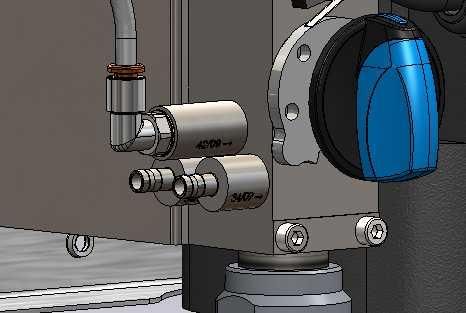
Due to the following it is very important 7.1.4. Adjustment of Sanitation
to close the water suplly when the unit Remove cover from the unit.
not in use. Adjustment of the sanitation can be done by means of
a limiting nozzle.
• If the water supply is left open when The limiting nozzle is placed in the suction nipple
the unit is not in use, water might of the non-retur valve (See picture no. 110003744)
seep into the product pick up line if and can be replaced with a smaller or larger nozzle
the non-return valve on the injector depending on the concentration needed, please also
block is leaking - which means that see table for guidelines.
the product can might be filled with
water. All tests have been made with P3 Sterill.
7.1.3. Adjustment of detergent
Remove cover from the unit.
Adjustment of detergent can be done by means of a
limiting nozzle (layout drawing).
Nozzle colour Concentration by 0,7 MPa in %
The limiting nozzle is placed in the suction nipple Orange 3,3
of the non-retur valve (See picture no. 110003744) Brown 2,9
and can be replaced with a smaller or larger nozzle Yellow 2,7
depending on the concentration needed, please also
Turquoise 1,7
see table for guidelines.
Purple 1,4
Light blue 0,9
Pink 0,6
In order to get your equipment adjusted properly we
recommend that your chemical supplier adjust it for
you.
7.1.5. Adjustment of air
Disinfection
Normally the Air will not need adjustment on the unit.
on
Foam If adjustment is necessary.
Do not attempt to adjust the Air your self always con-
tact am authorised service company.
} WARNING:
110003744 When working on the compressor be
care full, several parts of the Com-
pressor may be very hot.
All tests have been made with 7.2. Maintenance, trouble shooting and Service
Foamguard Hero 10. Maintenance Instructions
1. Quick couplings; it is recommended to lubricate
Nozzle colour Concentration by 0,7 MPa in % all couplings parts regularly, approx. once a year)
Orange 3,1 by water proof grease to prevent leaks and dam-
Brown 2,9 age of o-rings.
2. If the quick couplings leak, o-rings should be
Yellow 2,4
replaced.
Turquoise 1,7 3. Depending on usage, maintenance should be
Purple 1,4 undertaken by an authorised service engineer at
Light blue 1,1 least once a year in order to prevent defects and
Pink 0,8 failure of operation. Authorised engineers are
In order to get your equipment adjusted properly we persons who due to their skills and experience
recommend that your chemical supplier adjust it for have sufficient knowledge of Hygiene Systems
you . and are confident with the state work safety regu-
lations, accident preventing regulations, lines and
18English (EN)
generally acknowledged technical regulations line if the non-return valve on the injector block is
such as DIN-norms and VDE-provisions. For leaking.
your safety, this cleaning unit has been manufac- Water seeping back in to the product pick up line will
tured according to all relevant regulations valid dilute the product in the can and this will effect the
in the EU and therefore it has been supplied with foam quality when foaming with the unit.
the CE-marking. For further information, please CAUTION
refer to the service department. The chemical supply must always be
4. When the cleaning process has been completed rinsed thoroughly after use
or chemicals have been changed, it is important
to rinse the suction and injector systems in the
5. The following procedure will clean the chemical
following way:
supply for detergents and/or remains of disinfect-
• Replace the can with a can containing clean
ants.
water.
6. 1. Remove User Pack or the cans.
• Put the suction hose into the water can.
7. 2. Hold the rinsing bottle with clean water tightly
• Connect the foam nozzle.
against the suction opening (with User Pack).
• Open the spray gun/outlet valve and keep it open
Alternatively, you can place a User Pack with
until the injector has been rinsed through
clean water in the holder or – without User Pack
(approx. 30 seconds).
– place the hose in a bucket of clean water.
• Remove the suction hose from the water can.
8. 3. Activate the hose handle until clean water
5. It is recommended to delime the unit according to
comes out of the nozzle (approx. 30 seconds)
pharagraph 9.3
6. It is recommended to clean the surface inside the
unit at least once a month in order to maintain 9. Maintenance, Trouble shooting,
parts and avoid corrosion of parts. Service
CAUTION
8. Operation Before doing any maintenance, trou-
bleshooting or service make sure
8.1. Before Operation
that the unit and the parts in the unit
Make sure that the carrying capacity of the wall is
are not to hot to handle.
sufficient before mounting the unit to the wall, use ap-
propriate screws and dowels when mounting the unit.
CAUTION
The pipeline must be rinsed through Before doing any maintenance, trou-
before the system is connected. bleshooting or service make sure
that the power supply is discon-
nected, keep the plug close to you
Remove cover before the unit is mount- at all times to prevent someone from
ed on the wall. accidentally reconnecting the power
supply while you are working on the
unit..
8.2. Start/Stop (change, rinse, foam, des) 9.1. Preventive maintenance
Depending on usage, maintenance should be un-
Start the unit
dertaken by an authorised service engineer at least
1. Check that the power supply is conneted and the
once a year in order to prevent defects and failure of
water supply for the system is open.
operation. Authorised engineers are persons who due
2. Select requested function. Use the unit according
to their skills and experience have sufficient knowl-
to the ”User Guide”.
edge of the Hygiene Systems and are confident with
Stop the unit
the state work safety regulations, accident preventing
3. Disconnect the power supply
regulations, lines and generally acknowledged techni-
4. Close the water supply
cal regulations such as DIN-norms and VDE-provi-
It is important to close the water when
sions. For your safety, this cleaning unit has been
the unit is left after use .
manufactured according to all relevant regulations
valid in the EU and therefore it has been supplied with
• If the water supply is left open when the unit is not the CE-marking. For further information, please refer
in use, water might seep int othe product pick up to the service department.
19English (EN)
9.2. Rinsing the chemical supply/injector system °dH ppm Time between Deliming
The chemical supply must always be 0-5 18-90 12 months
rinsed thoroughly after use. 5-10 90-180 6 to 12 months
10-15 180-270 3 to 6 months
Remains of detergents or disinfectants can clog the 15-20 270-360 3 to 6 months
injector so it needs to be rinsed or replaced. >20 >360 1 to 3 months
The following procedure will clean the chemistry sup-
ply for detergents and/or remains of disinfectants. 9.4. Coupling
1. Remove User Pack or cans. It is recommended to lubricate all coupling parts regu-
2. Hold the rinsing bottle with clean water tightly larly (approx. once a month) with waterproof grease
against the suction opening (with User Pack) or to prevent leaks and damage of packings. If the unit
against the hose (without User Pack). Alternati- is equipped with a spray gun the piston of the gun
vely, you can place a User Pack with clean water should also be lubricated.
in the holder or – without User Pack – place the In leaking quick couplings the O-rings should be
hose in a bucket of clean water. replaced.
3. Activate the hose handle until clean water comes 9.5. Internal cleaning of the unit
out of the nozzle (approx. 30 seconds). We recommend opening and cleaning the unit inside
This procedure should be min. once a month.
followed both on the detergent
and the disinfectant side.
9.3. Deliming
• Disconnect the power supply.
• Disconnect the pick up hose from the detergent
non return valve on the injector block.
• Prepare the deliming fluid.
• Connect the deliming fluid to the detergent non
return valve on the injector block.
• Change the unit to the foam function.
• Activate the hose handle until all of the delimning
fluid has been sucked in to the injector block.
• Wait 5 minutes.
• Connect clean water to the detergent non return
valve on the injector block.
• Activate the hose handle until all of the clean wa-
ter has been sucked in to the injector block.
• Remove the temporary pick up hose and reinstall
the original pick up hose.
• Reconnect the power supply.
• Test the unit in Foam position make sure the vacu-
um is sufficient, it is recommended to be between
14,8 - 20,7 inHg / -0.05 - 0.07 MPa.
• Test that the unit can start and stop in both foam
and rinse position
• Reinstall the cover on the unit
The following deliming interwals must be observed to
prevent lime building up in the unit, that can discon-
tinue operation of the unit
20English (EN)
9.6. Trouble Shooting and Remedy
Fault Cause Remedy
No pressure with rinse nozzle No water supply. Open water supply valve.
Rinsing nozzle not installed. Place rinsing nozzle.
Contact your local service techni-
cian.
No foam with foam nozzle. Foam nozzle not installed Place foam nozzle.
Type of chemical product not suit- Change to correct type of chemi-
able. cal product.
Chemical limiting nozzle is blocked. Change metering tip.
No sanitising spray with spray Spray nozzle not installed. Place spray nozzle.
nozzle.
Sanitiser limiting nozzle is blocked. Shange metering tip.
Contact your local service techni-
cian.
In case of errors/troubles not mentioned above, please contact your local service technician for further assis-
tants, do not attempt to service the unit your self.
9.7. Service address
Please see the back cover of this manual
21English (EN)
10. Tools
Standard tools that are useful/necessary for service and maintenance on the full range of equipment.
Nose pliers 27 mm adjustable wrench
Ring spanner keys: Screw drivers:
14, 12 , 10, 8 mm Phillips PH2
Phillips PH0
Torx TX6
Slot 0,5x3,0x80mm
Allan keys:
2x5 mm
12, 4 , 3 mm
22English (EN)
11. End of Use
11.1. Dismounting
Disconnect the power supply.
Close and disconnect the water supply.
Remove the unit from the wall.
11.2. Disposal
In case the unit should be disposed, it must be sepa-
rated and sorted in eg-recyclable and non recyclable
parts.
The steel construction is easily separated and dis-
posed and constitutes no environmental risk - nor for
the user.
Disposal must be made according to rules and regula-
tions in force for disposal of machines as well as all
standards in connection with environmental protection.
CAUTION
Disposal of electronic components
and other remedies must be handled
as special disposal when disposed.
Alternatively, it can be disposed by a
specialised disposal company.
23Deutsch (DE)
24
DE1. Inhalt
1. Inhalt. . . . . . . . . . . . . . . . . . . . . . . . . . . . . . . . . . . . . . . . . . . . . . . . . . . . . . . . . . . . . . . . . . . . . . . . . . . . . . . . . . . . . . . . . . . . . . . . . . . . . 25
2. In diesem Dokument verwendete Symbole ������������������������������������������������������������� 26
3. Allgemeine Informationen ������������������������������������������������������������������������������� 27
3.1. Layout for Griff... . . . . . . . . . . . . . . . . . . . . . . . . . . . . . . . . . . . . . . . . . . . . . . . . . . . . . . . . . . . . . . . . . . . . . . . . . . . . . . . . . . . 28
3.2. Betriebspläne .. . . . . . . . . . . . . . . . . . . . . . . . . . . . . . . . . . . . . . . . . . . . . . . . . . . . . . . . . . . . . . . . . . . . . . . . . . . . . . . . . . . . . 29
3.3. Kennzeichnungsschild ������������������������������������������������������������������������������ 30
3.4. Anbieter.. . . . . . . . . . . . . . . . . . . . . . . . . . . . . . . . . . . . . . . . . . . . . . . . . . . . . . . . . . . . . . . . . . . . . . . . . . . . . . . . . . . . . . . . . . . 30
3.5. Spezifikationen.. . . . . . . . . . . . . . . . . . . . . . . . . . . . . . . . . . . . . . . . . . . . . . . . . . . . . . . . . . . . . . . . . . . . . . . . . . . . . . . . . . . . 31
4. Überblick und Gebrauch. . . . . . . . . . . . . . . . . . . . . . . . . . . . . . . . . . . . . . . . . . . . . . . . . . . . . . . . . . . . . . . . . . . . . . . . . . . . . . . . . 32
Deutsch (DE)
5. Systemsicherheit. . . . . . . . . . . . . . . . . . . . . . . . . . . . . . . . . . . . . . . . . . . . . . . . . . . . . . . . . . . . . . . . . . . . . . . . . . . . . . . . . . . . . . . . . 32
5.1. Verschlussventil für Wasserversorgung �������������������������������������������������������������� 32
5.2. Voraussichtliche Ausfälle ��������������������������������������������������������������������������� 32
5.3. Restrisiko. . . . . . . . . . . . . . . . . . . . . . . . . . . . . . . . . . . . . . . . . . . . . . . . . . . . . . . . . . . . . . . . . . . . . . . . . . . . . . . . . . . . . . . . . . 32
6. Installation. . . . . . . . . . . . . . . . . . . . . . . . . . . . . . . . . . . . . . . . . . . . . . . . . . . . . . . . . . . . . . . . . . . . . . . . . . . . . . . . . . . . . . . . . . . . . . . . 33
6.1. Störgeräusche.. . . . . . . . . . . . . . . . . . . . . . . . . . . . . . . . . . . . . . . . . . . . . . . . . . . . . . . . . . . . . . . . . . . . . . . . . . . . . . . . . . . . . 33
6.2. Anweisungen zur Montage der Wandversion ��������������������������������������������������������� 33
6.3. Anweisungen zur Montage der Trolley-Version ������������������������������������������������������� 33
6.4. Transport.. . . . . . . . . . . . . . . . . . . . . . . . . . . . . . . . . . . . . . . . . . . . . . . . . . . . . . . . . . . . . . . . . . . . . . . . . . . . . . . . . . . . . . . . . . 33
6.5. Vibrationen.. . . . . . . . . . . . . . . . . . . . . . . . . . . . . . . . . . . . . . . . . . . . . . . . . . . . . . . . . . . . . . . . . . . . . . . . . . . . . . . . . . . . . . . . 33
6.6. Elektroanschluss.. . . . . . . . . . . . . . . . . . . . . . . . . . . . . . . . . . . . . . . . . . . . . . . . . . . . . . . . . . . . . . . . . . . . . . . . . . . . . . . . . . . 33
6.7. Wasseranschluss.. . . . . . . . . . . . . . . . . . . . . . . . . . . . . . . . . . . . . . . . . . . . . . . . . . . . . . . . . . . . . . . . . . . . . . . . . . . . . . . . . . 33
6.8. Luftzufuhr.. . . . . . . . . . . . . . . . . . . . . . . . . . . . . . . . . . . . . . . . . . . . . . . . . . . . . . . . . . . . . . . . . . . . . . . . . . . . . . . . . . . . . . . . . 34
6.8.1. Einspeisung chemischer Produkte 34
6.9. Schlauchverbindung ������������������������������������������������������������������������������� 34
7. Betriebsverfahren.. . . . . . . . . . . . . . . . . . . . . . . . . . . . . . . . . . . . . . . . . . . . . . . . . . . . . . . . . . . . . . . . . . . . . . . . . . . . . . . . . . . . . . . . 34
7.1. Inbetriebnahme.. . . . . . . . . . . . . . . . . . . . . . . . . . . . . . . . . . . . . . . . . . . . . . . . . . . . . . . . . . . . . . . . . . . . . . . . . . . . . . . . . . . . 34
7.1.1. Start 34
7.1.2. Stopp 34
7.1.3. Einstellung des Reinigungsmittels 35
7.1.4. Einstellung der Desinfektion ������������������������������������������������������������������� 35
7.1.5. Einstellung der Luft ��������������������������������������������������������������������������� 35
7.2. Wartung, Problemanalyse und Kundendienst �������������������������������������������������������� 35
8. Betrieb.. . . . . . . . . . . . . . . . . . . . . . . . . . . . . . . . . . . . . . . . . . . . . . . . . . . . . . . . . . . . . . . . . . . . . . . . . . . . . . . . . . . . . . . . . . . . . . . . . . . . 36
8.1. Vor dem Betrieb .. . . . . . . . . . . . . . . . . . . . . . . . . . . . . . . . . . . . . . . . . . . . . . . . . . . . . . . . . . . . . . . . . . . . . . . . . . . . . . . . . . 36
8.2. Start/Stopp . . . . . . . . . . . . . . . . . . . . . . . . . . . . . . . . . . . . . . . . . . . . . . . . . . . . . . . . . . . . . . . . . . . . . . . . . . . . . . . . . . . . . . . . 36
9. Wartung, Problemanalyse und Kundendienst ���������������������������������������������������������� 36
9.1. Vorbeugende Wartung ����������������������������������������������������������������������������� 36
9.2. Spülung der chemischen Versorgung/des Injektorsystems �������������������������������������������� 37
9.3. Entkalken. . . . . . . . . . . . . . . . . . . . . . . . . . . . . . . . . . . . . . . . . . . . . . . . . . . . . . . . . . . . . . . . . . . . . . . . . . . . . . . . . . . . . . . . . . 37
9.4. Kupplung.. . . . . . . . . . . . . . . . . . . . . . . . . . . . . . . . . . . . . . . . . . . . . . . . . . . . . . . . . . . . . . . . . . . . . . . . . . . . . . . . . . . . . . . . . . 37
9.5. Innenreinigung des Geräts �������������������������������������������������������������������������� 37
9.6. Fehlersuche und Behandlung ����������������������������������������������������������������������� 38
9.7. Serviceadresse.. . . . . . . . . . . . . . . . . . . . . . . . . . . . . . . . . . . . . . . . . . . . . . . . . . . . . . . . . . . . . . . . . . . . . . . . . . . . . . . . . . . . 38
10. Werkzeuge.. . . . . . . . . . . . . . . . . . . . . . . . . . . . . . . . . . . . . . . . . . . . . . . . . . . . . . . . . . . . . . . . . . . . . . . . . . . . . . . . . . . . . . . . . . . . . . . . 39
11. Nach der Verwendung. . . . . . . . . . . . . . . . . . . . . . . . . . . . . . . . . . . . . . . . . . . . . . . . . . . . . . . . . . . . . . . . . . . . . . . . . . . . . . . . . . . . . 40
11.1. Demontage .. . . . . . . . . . . . . . . . . . . . . . . . . . . . . . . . . . . . . . . . . . . . . . . . . . . . . . . . . . . . . . . . . . . . . . . . . . . . . . . . . . . . . . 40
11.2. Entsorgung. . . . . . . . . . . . . . . . . . . . . . . . . . . . . . . . . . . . . . . . . . . . . . . . . . . . . . . . . . . . . . . . . . . . . . . . . . . . . . . . . . . . . . . 40
25Sie können auch lesen